Installation – Casella CEL Multimet User Manual
Page 8
1.2.4 Expansion Socket
The Expansion socket provides signals used for CAN
TM
bus display
networking and interfacing to an external alarm circuit.
Expansion Socket (9 way “D” type female) pinout
Function
Pin Number
CAN Bus “A”
2
CAN Bus “B”
3
Cable screen connection
5
TTL alarm output
9
Alarm ground
8
1.2.5 Networking Multiple Displays
In a networked system, the master display unit (connected to the sensors)
will automatically transmit real-time wind data to all interconnected displays.
The CAN bus A and B signals on all networked displays should be
interconnected using a twisted-pair cable. The maximum total cable length of
the network should be <3 km.
1.2.6 Alarm Output
The alarm signal level is normally low (0 V) and will go high (5 V) whenever an
alarm condition occurs. The maximum source or sink current available from
this signal line is 5 mA. Suitable interface circuitry is required to control higher
powered warning devices or systems. To avoid communication errors and
conflicts, the EXT Alarm should be set to OFF whenever the RS232
connection is required.
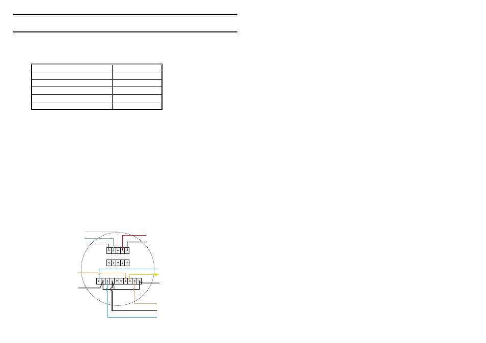
1.2.7 Wiring Details for Panel Mounted Displays
Panel mounted displays are supplied with a basic cable loom for connecting
sensors, power supply and communications. Modifications to the basic cable
loom may be required to suit specific installation requirements. Connection
details for the rear of the display are shown.
(Blue) RX
(Yellow) TX
(Black) 0 V
(Red/Centre pin) +12 V
(Black/Outer) 0 V
SENSOR
(Violet) Screen
(Green) CAN bus "B"
(White) CAN bus "A"
(Orange)
Alarm Out
(Black)
Ground
02074
EXPANSION CONNECTOR
POWER
SOCKET
RS232
(Brown) +12 V
(Black) 0 V
(Blue) DATA
Pin1
Installation
Page 8 of 16
MULTIMET Wind Speed and Direction System
& OnlinePro Software - Users Handbook