CIRCUTOR OPTIM-FR Series User Manual
Page 12
Instruction Manual
10
6
START-UP OF A CAPACITOR BANK WITH DETUNED FILTERS
6.1
Before start-up
Automatic capacitor banks with FR filters have a built-in power factor regulator. Prior to start-up,
the operation of said regulator must be known; for this reason, all filter banks come with the
specific manual of the regulator used. Ensure you have this manual available for the start-
up process.
The adjustment of the built-in regulator of filter banks with and its optimum start-up
requires the installation to have at least a 30 to 40% nominal load for which the
filter bank was dimensioned. If all the stages are not included, they can be
manually connected to check them all.
During low charge periods, manually connecting the entire filter bank is not
recommended, as in some cases resonance with the installation power
transformer could occur.
For manual connections of the LC steps, remember that you must wait until the
capacitors have been discharged before they can be connected to the grid,
otherwise, the system could start up having a transient voltage of up to 2xUn,
causing current peaks in the capacitors.
6.2
Start-up
SAFETY
Apply the safety regulations listed in section 2 of this manual before operating the
equipment.
The standards and applicable national regulations of the country where the filter
bank is installed or operated should be strictly followed.
•
Ensure that the inner circuit breaker supplying the regulator (shown as the operating protection
in fig. 4.3) is connected
•
Apply power to the panel and check that the regulator display illuminates immediately. If not,
stop and check the previous step.
•
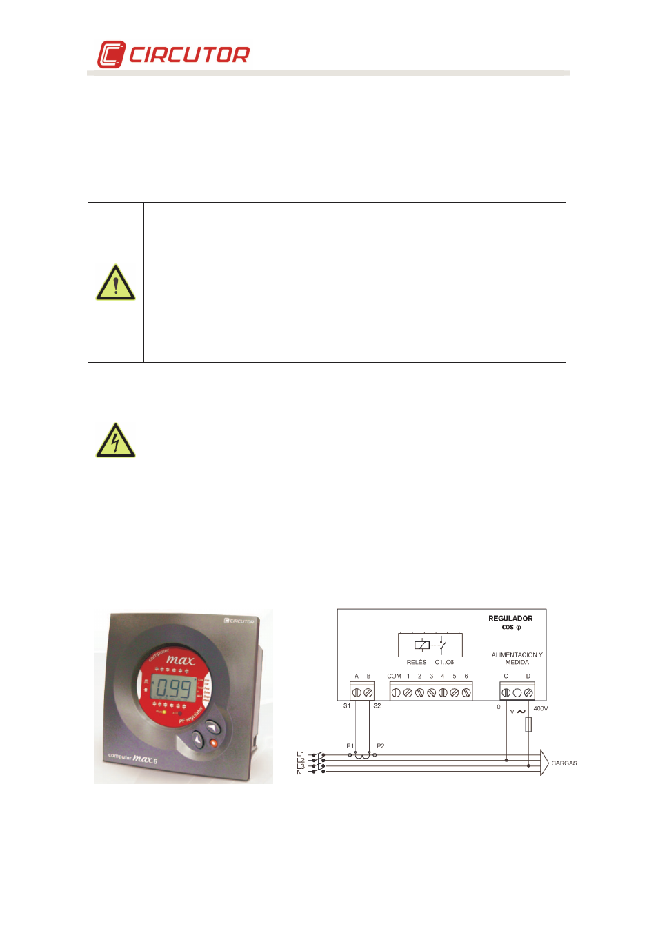
Check the regulator's cos
ϕ
indication. If the indication is out of range 0.5 to 1, the current
transformer and / or the power supply to the regulator may be improperly connected. Most of
the regulators use only one current transformer. In this case, connect as per fig. 6-2 (place the
current transformer in phase L1 and take the power voltage from phases L2 and L3)
Fig. 6-1 .- Computer Max Regulator
(Picture provided as an example. It may not
coincide with the model used on your unit).
Fig. 6-2 .- Standard connection of a regulator with a
single TC
(3 current transformers will be used when Computer +
is used. See the specific manual of the Computer + regulator)