Lan module slot – NEXCOM NSA 5150 User Manual
Page 43
Copyright © 2013 NEXCOM International Co., Ltd. All Rights Reserved.
29
NSA 5150 User Manual
Chapter 2: Jumpers and Connectors
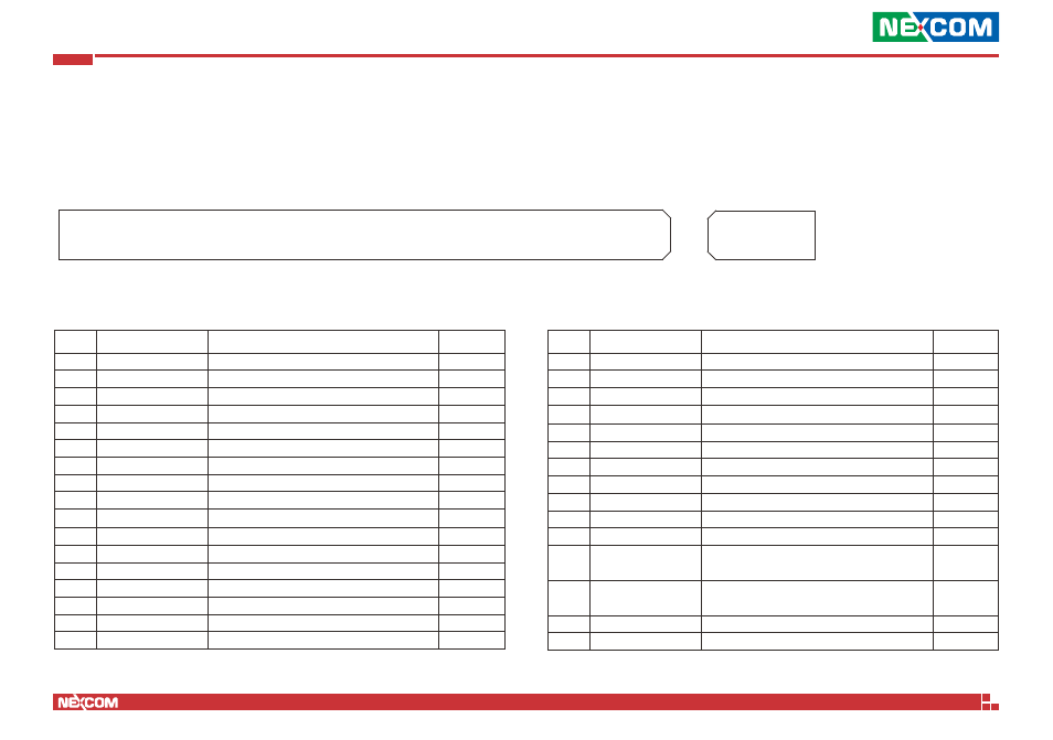
LAN Module Slot
Connector location: U3
A1
A11
B1
B11
A12
A82
B12
B82
Pin
Definition
Pin
Direction
A1
GND
GND
A2
LPC_AD0
LPC Multiplexed Command, Address, Data
I/O
A3
LPC_AD1
LPC Multiplexed Command, Address, Data
I/O
A4
LPC_AD2
LPC Multiplexed Command, Address, Data
I/O
A5
LPC_AD3
LPC Multiplexed Command, Address, Data
I/O
A6
LPC_FRAME_N
LPC Frame
O
A7
GND
GND
A8
CK_33M_PCIE1
33MHz Clock output
O
A9
GNG
GND
A10
PCIE1_SLOT_RST_N
Platform Reset
O
A11
GND
GND
A12
P5V
5V
Power
A13
P5V
5V
Power
A14
P5V
5V
Power
A15
P5V
5V
Power
A16
P5V
5V
Power
A17
P3V3
3.3V
Power
Pin
Definition
Pin
Direction
A18
P3V3
3.3V
Power
A19
P3V3
3.3V
Power
A20
P3V3
3.3V
Power
A21
P3V3
3.3V
Power
A22
P3V3
3.3V
Power
A23
P3V3
3.3V
Power
A24
P12V
12V
Power
A25
P12V
12V
Power
A26
P12V
12V
Power
A27
P12V
12V
Power
A28
P12V
12V
Power
A29
ATX_PWROK_B1
Power good signal from ATX power supply
8.2K pull-high to 5VDual
O
A30
ATX_PWROK_B2
Power good signal from ATX power supply
8.2K pull-high to 5VDual
O
A31
GND
GND
A32
PCIE1_SMBCLK
SMBus Clock. 4.7K pull-high to 3.3V
I/O
A82
A12
B12
B11
A11
A1
B1
B82