Register bit definitions – NEXCOM NSA 5150 User Manual
Page 83
Copyright © 2013 NEXCOM International Co., Ltd. All Rights Reserved.
69
NSA 5150 User Manual
Appendix A: Bypass Register
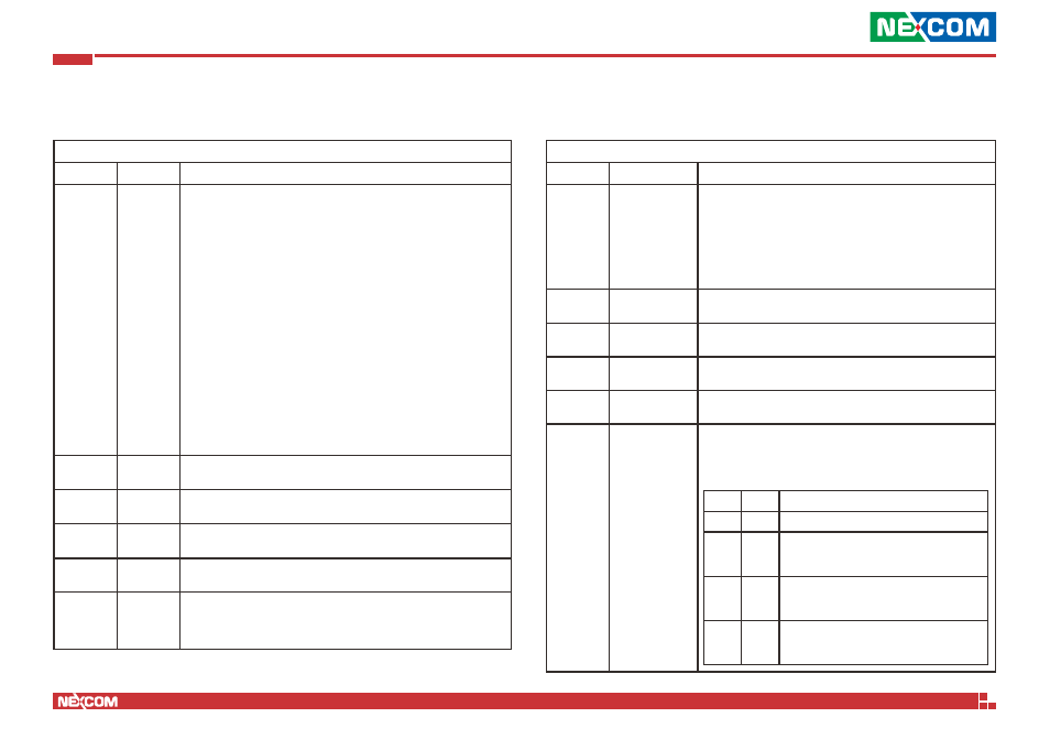
Bypass Timer Configuration Register (F2)
Bit Field
Name
Value
2:0
Timer
Value
000 = 0 second, timer immediately expired
001 = 1 second
010 = 2 second
011 = 4 second
100 = 8 second
101 = 16 second
110 = 32 second
111 = 64 second
Note: This is a write only field.
Upon reads these bit values are undefined.
A Timer value of 1 to 7 is required to be written before expiration
of the hardware timer. When the timer expires, all segments which
have been enabled in bits 2:0 of Power ON state Bypass Control
Status Register set relays closed to form bypass segments. It is
responsibility of software to keep track of time to ensure writes to
this register occur no greater than TimerValueInSeconds / 2. A write
of the timer value will automatically reset the expiration timer and
set it to the value expressed in bit 2:0 .
3
Not used
No active taken if written, value is undetermined and not
needed on read operation.
4
Not used
No active taken if written, value is undetermined and not
needed on read operation.
5
Not used
No active taken if written, value is undetermined and not
needed on read operation.
6
Not used
No active taken if written, value is undetermined and not needed
on read operation.
7
Segment
Timer
Expired
Read only bit:
0 = Timer has not expired
1 = Timer has expired, de-assert while leave Timer mode
Register Bit Definitions
Power ON State Bypass Control Status Register (F3)
Bit Field
Name
Value
1:0
Segment 1 to 2
Segment control bit mask. Each bit corresponds to a specific
segment numbered 1 through 2.
Write:
If a segment mask bit is set to false (0) no action on that
segment will take place.
If a segment mask bit has been set to true (1), action will
take place on this segment according to the bypass mode
settings in bits 7:6.
2
Not used
No active taken if written, value is undetermined and not
needed on read operation.
3
Not used
No active taken if written, value is undetermined and not
needed on read operation.
4
Not used
No active taken if written, value is undetermined and not
needed on read operation.
5
Not used
No active taken if written, value is undetermined and not
needed on read operation.
7:6
Bypass Mode
These two bits defined the bypass mode for one or more
segments. These bits are Write only and on reads returns
undetermined values which will be ignored by the driver.
Bypass Mode Table:
Bit 7
Bit 6
Action
0
0
Ignore, no action taken
0
1
Force Enable:
Engage bypass relays on segments enabled in
segment mask.
1
0
Force Disable:
Disable bypass relays immediately on segments
enabled in mask.
1
1
Timer Enable:
Segments enabled in mask are under Timer
control.