Dca-2 callouts, Rc-16 callouts – Oxmoor DCA-2 User Manual
Page 4
DCA-2 DIGITAL CONTROL ATTENUATOR
POWER
CHANNEL A
CHANNEL B
1
Page 2
CHASSIS
SERIAL #
POWER
FUSE
OUTPUT
IN
OUT
IN
OUT
REMOTE CONTROLS
CHANNEL B
CHANNEL A
PRESET
PRIORITY
CHAN A
INPUT
OUTPUT
CHAN B
OXMOOR
MADE IN USA BY
OXMOOR CORPORATION
BIRMINGHAM, ALABAMA
INPUT
5
DCA-2 CALLOUTS
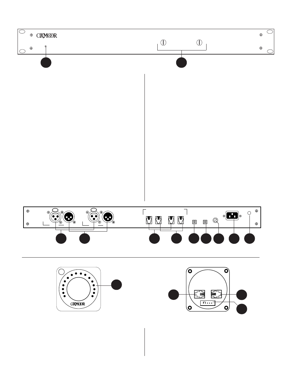
together. Provides connections to PRESET, PRIORITY,
COUNT UP, COUNT DOWN, COMMON.
7.
PRESET CONTROL
- Binary pot, adjusted using a small flat-
blade screwdriver. It is used to determine the default
attenuation level. The DCA-2 returns to the PRESET level
whenever it is powered up or the PRESET control line is
momentarily taken to COMMON.
8.
PRIORITY CONTROL
- Binary pot, adjusted using a small flat-
blade screwdriver. It is used to determine the PRIORITY
attenuation level. The DCA-2 goes to the PRIORITY level
whenever the PRIORITY control line is taken to COMMON.
9.
FUSE HOLDER
- Replace only with approved type of fuse
in a rating appropriate to the mains voltage, as indicated
on back panel (see SPECIFICATIONS, page 13).
10. POWER CONNECTOR
- Standard IEC 3-pin connector for
AC power cord. Use only with grounded (3-wire) outlets.
Cord sets are available for all world connection
standards.
11. CHASSIS GROUND POST
- A screw with a star washer
enables the installer to secure a ground wire to the
chassis.
Figure 1.0: DCA-2 Front Panel View
1.
POWER STATUS LED
- Indicator for AC Power On.
2.
INPUT TRIM
- Trim pots, accessed through the front panel
with a small flat-blade screwdriver, offer ±15 dB gain
adjustment to match different operating levels or balance
levels across channels.
3.
PROGRAM INPUTS
- Audio input, XLR-F–type connector, Pin
2 positive, electronically balanced, accepts balanced or
unbalanced signals from line-level devices. Normal input
level is +4 dBu with a maximum input level of +20 dBu.
4.
PROGRAM OUTPUTS
- Audio outputs, XLR-M–type
connectors, Pin 2 positive, unbalanced. Recommended
load impedance is 600 ohms or greater. Maximum
output level is +20 dBu.
5.
REMOTE CONTROL INPUTS
- Six-conductor modular
telephone jacks. Used to interface external remote control
devices. Provides connections to PRESET, PRIORITY,
COUNT UP, COUNT DOWN, DISPLAY/POWER,
COMMON.
6.
REMOTE CONTROL OUTPUTS
- Six-conductor modular
telephone jacks. Used to link the remote control channels
Figure 1.1: DCA-2 Rear Panel View
6
3
4
11
7
9
10
8
3.
REMOTE CONTROL INPUT
- Six-conductor modular telephone
jacks. Used to link to the next RC-16 Remote Control.
4.
CONTROL PORT
- Single line, five-pin header, used to
extend KEY SWITCH, PRESET, and PRIORITY functions
at the remote control location.
1.
VIRTUAL POINTER
- LED indicates the current volume
setting.
2.
REMOTE CONTROL OUTPUT
- Six-conductor modular
telephone jacks. Used to link the remote control to the
DCA-2’s “IN” jack.
RC-16 CALLOUTS
2
C
1
IN
OUT
OXMOOR
RC-16
1
5
2
3
4
Figure 1.3: RC-16 Rear Panel View
Figure 1.2: RC-16 Front Panel View