Dca-2 & rc-16 connections, Page 5, Figure 5.5: rc-16 pin-outs – Oxmoor DCA-2 User Manual
Page 7
123456
PRIORITY
DISPLAY
COUNT UP
COUNT DOWN
COMMON
PRESET
123456
PRIORITY
DISPLAY
COUNT UP
COUNT DOWN
COMMON
PRESET
1 2 3 4 5
PRIORITY
COMMON
PRESET
Provision for Security Key:
A jumper is factory installed.
+
–
S
SHIELD
HIGH
LOW
2
3
1
XLR PIN-OUT
+
–
S
LOW
HIGH
NC
2
3
1
XLR PIN-OUT
BALANCED (DCA-2T VERSION)
BALANCED (DCA-2T VERSION)
BALANCED (DCA-2T VERSION)
BALANCED (DCA-2T VERSION)
BALANCED (DCA-2T VERSION)
Page 5
DCA-2 & RC-16 CONNECTIONS
DCA-2 PROGRAM INPUT AND OUTPUT CONNECTIONS
(Refer to Figure 5.0)
The DCA-2 Digital Control Attenuator provides connections
for two program channels. The unit can operate as a two
channel mono or as a stereo unit.
The Program Input connections are made through female,
XLR-type, 3-pin connectors. The Program Output connections
are made through male XLR-type 3-pin connectors.
DCA-2 PROGRAM INPUTS
(Refer to Figure 5.1)
DCA-2:
Pin 1 = Shield, Pin 2 = High, Pin 3 = Low, electronically
balanced inputs accept balanced or unbalanced signals from
line-level devices. Nominal input level is +4 dBu with
maximum input level of +20 dBu.
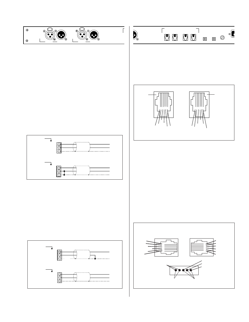
DCA-2 PIN-OUTS FOR REMOTE CONTROL
(Refer to Figure 5.4)
The DCA-2 Digital Control Attenuator provides female 6-pin
modular TELCO connectors for interface to the Oxmoor
RC-16.
Figure 5.3: Remote Control Inputs and Outputs
Figure 5.0: Program Inputs and Outputs
OUTPUT
CHAN A
INPUT
OUTPUT
CHAN B
OXMOOR
MADE IN USA BY
OXMOOR CORPORATION
BIRMINGHAM, ALABAMA
INPUT
DCA-2 PROGRAM OUTPUTS
(Refer to Figure 5.2)
DCA-2:
Pin 1 = Shield, Pin 2 = High, Pin 3 = Low, electronically
unbalanced outputs. Recommended load impedance is 600
ohms or greater. Maximum output level is +20 dBu.
DCA-2T:
Pin 1 = Shield, Pin 2 = High, Pin 3 = Low, electronically
balanced outputs accommodate balanced or unbalanced lines.
Recommended load impedance is 600 ohms or greater.
Maximum output level is +20 dBu.
P
FUSE
TPUT
IN
OUT
IN
OUT
REMOTE CONTROLS
CHANNEL B
CHANNEL A
PRESET
PRIORITY
OXMOOR
MADE IN USA BY
OXMOOR CORPORATION
BIRMINGHAM, ALABAMA
1 2 3 4 5 6
1 2 3 4 5 6
PPRESET
COMMON
COUNT DOWN
COUNT UP
DISPLAY
PRIORITY
PRIORITY
NC
COUNT UP
COUNT DOWN
COMMON
PRESET
OUT
OUT
OUT
OUT
OUT
IN
IN
IN
IN
IN
Figure 5.4: Remote Control Input and Output Pin-Outs
RC-16 PIN-OUTS
(Refer to Figure 5.5)
The RC-16 Remote Control provides female 6-pin modular
TELCO connectors for interface to the Oxmoor DCA-2
Digital Control Attenuator and other RC-16 Remote Controls.
Connect the OUT jack of the RC-16 to the IN jack of the
DCA-2. If using round cable, it is important to connect the
RC-16’s PRIORITY to the DCA-2’s PRIORITY, the RC-16’s
COUNT UP to the DCA-2’s COUNT UP, etc.
When “daisy-chaining” RC-16s, take the OUT jack of one
RC-16 to the IN jack of the next RC-16. You can “daisy-
chain” a total of eight RC-16s for each DCA-2 unit.
Figure 5.5: RC-16 Pin-Outs
Connect
to the
RC-16
OUT
jack
Use to loop
to next
DCA-2’s
INPUT if
both
channels
are to be
controlled
by one
remote
control
Connect to the DCA-2’s IN jack
Connect to next RC-16’s OUT jack
Remove jumper and
connect to KEY SWITCH
for security at remote location
Connect to
pushbuttons
to activate PRESET and
PRIORITY at remote location
OUT
OUT
OUT
OUT
OUT
IN
IN
IN
IN
IN
Figure 5.2: Program Output Wiring Schemes
Figure 5.1: Program Input Wiring Schemes
UNBALANCED
UNBALANCED
UNBALANCED
UNBALANCED
UNBALANCED
+
–
S
HIGH
LOW
SHIELD
+
–
S
HIGH
LOW
NC
2
3
1
XLR PIN-OUT
2
3
1
XLR PIN-OUT
UNBALANCED
UNBALANCED
UNBALANCED
UNBALANCED
UNBALANCED
BALANCED
BALANCED
BALANCED
BALANCED
BALANCED