Pinnacle Systems Universal Safety Controller HUB User Manual
Page 11
Advertising
Page 6 of 18
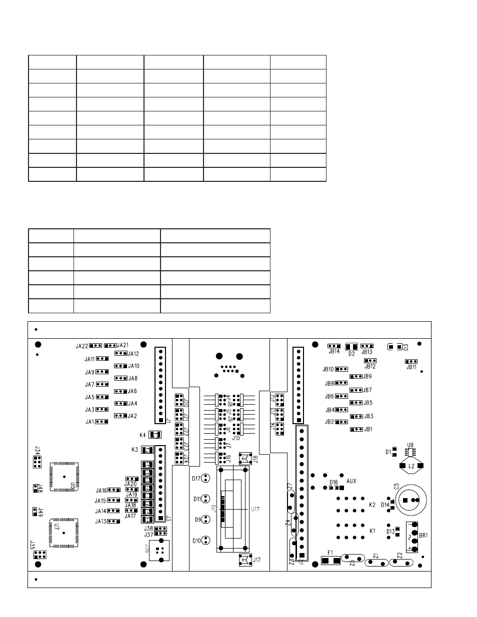
Internal Jumper Chart:
Terminal#
Internal Jumper
Function
Bottom 2 pins
Top 2 pins
B41-B52
JA1 – JA12
Input
Sourcing*
Sinking
A17-A28
JB1 – JB12
Input
Sourcing*
Sinking
E31-E38
JA13-JA20
Output
Sinking
Sourcing*
B51-B52
JA21-JA22
Mat
Set up for Mat
Std Input*
A27-A28
JB13-JB14
Mat
Set up for Mat
Std Input*
J48-J49
Reserved
J34-J35
Reserved
USB
J37-J38
Programming
Sourcing = +24vdc on Terminal#
Sinking = Ground on Terminal#
* Default position
Reference Chart:
Reference Function
Related
K1-K2
Channel C output
D13-D14 LEDS indicate ON
Aux
Channel C aux output
D16 LED indicates ON
K3-K4
Channel D output
F2-F3 .5A resetable fuses
F1
Controller Fuse
1A slo-blo Replaceable
D1
Power LED
Indicates 5v power
Advertising