Programming / ordering, Ordering/pricing procedure – Pinnacle Systems Universal Safety Controller HUB User Manual
Page 12
Page 7 of 18
Programming / Ordering
The Universal Safety Controller Hub is programmed by
the factory, but can be modified in the field by contacting
the factory (via email). (see page 17)
A Hub Model# is composed of a list of device and there
functions. Page 8 illustrates an example of a common
safety guarding application. Page 9 illustrates an
example of a sophisticated press control application (that
also includes guarding).
The full Model# format can include not only the device#
but the output you wish to control.
Universal Safety Hub Ordering Procedure.
Format Model#: SH‐XX(YY)‐XX(YY)‐XX(YY)‐… (where XX is the Input device type, where YY is an OPTIONAL Output device type)
Example Model#:
SH‐2‐2‐6‐10‐2‐2E‐6E‐8C (2 light curtains + 1 ESTOP tied to C with latching RESET, 1 light curtain + mat tied to C with no latching, 1 light
curtain + 1 ESTOP tied to D with no latching)
Custom programming optional.
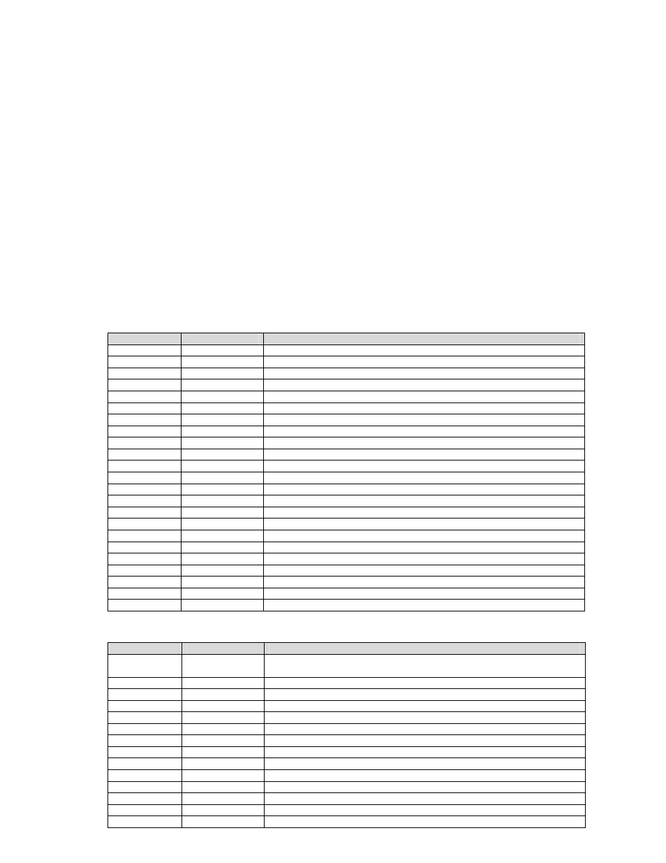
Current list of Input Device types:
XX
Terminals used
Input Device Type
1(T)
2
START or STOP or CANCEL button inputs
2
2
CAT 4 Light curtain or CAT 2 ESTOP
3
2
Foot Pedal
4
3
Cat 3 ESTOP input
5
Reserved
6
4
Cat 4 ESTOP input
7(T)
2
Palm button station (2 palm buttons) N.O. from each button
8
4
NSD Safety Mat or any 4-wire pressure sensor device
9(T)
2
Limit Switch (mechanical or Pressure)
10(T)
2
Reset Button for Channel C
11(T)
2
Reset Button for Channel D
12(T)
2
Cincinnati Interface for Channel C
13(T)
2
Cincinnati Interface for Channel D
14(T)
2
Mute-Out bypass for Channel C
15(T)
2
Mute-Out bypass for Channel D
16(T)
2
EDM (External Device Monitor) for Channel C
17(T)
2
EDM (External Device Monitor) for Channel D
18
Reserved
19
Reserved
20(T)
2
Key Switch bypass (used to bypass other devices)
21(T)
2
Prox sensor input (1/4” pinch point)
22(T)
2
Mute-Out bypass for Foot Switch device #3
23(T)
4
Palm button station (2 palm buttons) N.O. and N.C. from each button
(T) optional Timer function to allow time limits. User programmable times
Current list of Output Device types:
YY
Channel output
Output Device Type
C
Assume Devices use Channel C if left blank
Assume Device Status tied to each Channel E output
E
E
Device Status Output (default)
C
C
Devices tie to Channel C mechanical relays
D
D
Devices tie to Channel D solid state relays
240C
C
Timer function to hold Channel C ON
241C
C
Timer function to hold Channel C OFF
242D
D
Timer function to hold Channel D ON
243D
D
Timer function to hold Channel D OFF
251CD
C/D
Devices Latch C ON and D OFF
252CD
C/D
Devices Latch D ON and C OFF
253CD
C/D
Devices Latch both C & D OFF
254CD
C/D
ESTOP devices turn C & D OFF both
255CD
C/D
Devices turn C & D OFF both
Universal Safety Hub Ordering Procedure.
Format Model#: SH‐XX(YY)‐XX(YY)‐XX(YY)‐… (where XX is the Input device type, where YY is an OPTIONAL Output device type)
Example Model#:
SH‐2‐2‐6‐10‐2‐2E‐6E‐8C (2 light curtains + 1 ESTOP tied to C with latching RESET, 1 light curtain + mat tied to C with no latching, 1 light
curtain + 1 ESTOP tied to D with no latching)
Custom programming optional.
Current list of Input Device types:
XX
Terminals used
Input Device Type
1(T)
2
START or STOP or CANCEL button inputs
2
2
CAT 4 Light curtain or CAT 2 ESTOP
3
2
Foot Pedal
4
3
Cat 3 ESTOP input
5
Reserved
6
4
Cat 4 ESTOP input
7(T)
2
Palm button station (2 palm buttons) N.O. from each button
8
4
NSD Safety Mat or any 4-wire pressure sensor device
9(T)
2
Limit Switch (mechanical or Pressure)
10(T)
2
Reset Button for Channel C
11(T)
2
Reset Button for Channel D
12(T)
2
Cincinnati Interface for Channel C
13(T)
2
Cincinnati Interface for Channel D
14(T)
2
Mute-Out bypass for Channel C
15(T)
2
Mute-Out bypass for Channel D
16(T)
2
EDM (External Device Monitor) for Channel C
17(T)
2
EDM (External Device Monitor) for Channel D
18
Reserved
19
Reserved
20(T)
2
Key Switch bypass (used to bypass other devices)
21(T)
2
Prox sensor input (1/4” pinch point)
22(T)
2
Mute-Out bypass for Foot Switch device #3
23(T)
4
Palm button station (2 palm buttons) N.O. and N.C. from each button
(T) optional Timer function to allow time limits. User programmable times
Current list of Output Device types:
YY
Channel output
Output Device Type
C
Assume Devices use Channel C if left blank
Assume Device Status tied to each Channel E output
E
E
Device Status Output (default)
C
C
Devices tie to Channel C mechanical relays
D
D
Devices tie to Channel D solid state relays
240C
C
Timer function to hold Channel C ON
241C
C
Timer function to hold Channel C OFF
242D
D
Timer function to hold Channel D ON
243D
D
Timer function to hold Channel D OFF
251CD
C/D
Devices Latch C ON and D OFF
252CD
C/D
Devices Latch D ON and C OFF
253CD
C/D
Devices Latch both C & D OFF
254CD
C/D
ESTOP devices turn C & D OFF both
255CD
C/D
Devices turn C & D OFF both
Ordering/Pricing Procedure
Format Model#: SH-XX(YY)-XX(YY)-XX(YY)- …
(where XX is the Input device type, where YY is an OPTIONAL Output device type)
Example Model#: SH-2-2-6-10-2-2D-6D-8C
(2 light curtains + 1 ESTOP tied to C with latching RESET, 1 light curtain + mat tied to C with no latching,
1 light curtain + 1 ESTOP tied to D with no latching)
Current List of Input Device Types
Current List of Output Device Types
Terminals fill out terminals started from the left side (A17
and B41) and work right (except for mats which always
use A27/28 & B51/52
For more sophisticated applications, email the factory
with a full description of each device required and its
function (what does it control and when). The factory will
convert this into a Model#