Removing air trap, Plumbing – Toyotomi BS-35(F) User Manual
Page 23
7
CAUTION: If metal fuel pipe is laid-out, be sure to clear away scraps or chips from the pipe
which are produced during cutting or assembling. Leaving these scraps in the pipe
may cause problem in the fuel pump.
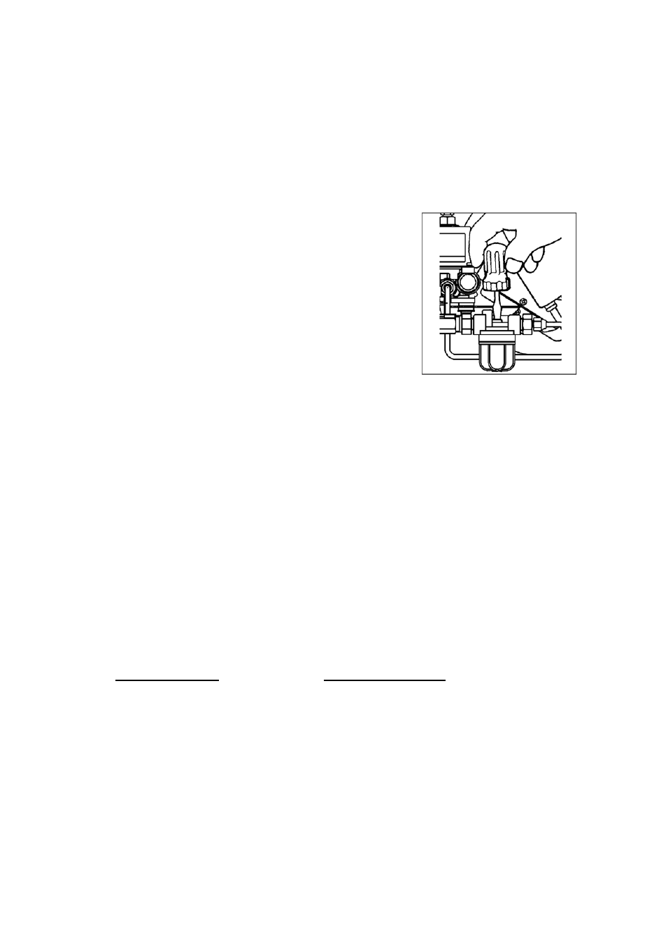
REMOVING AIR TRAP
When operating for the first time or when refueling an empty tank, air may be trapped in the
fuel line, making ignition difficult. In this situation, follow the procedure below:
1. Press “POWER SWITCH” to “OFF” position. Disconnect
the power supply cord.
2. To catch the fuel which will drain out, put a small
container under the strainer.
3. Loosen the screw on top of the strainer. Immediately wipe
off any spilled fuel.
4. Remove the trapped air thoroughly. Failure to remove all
the air will cause improper ignition and may extinguish
the unit.
5. Tighten the screw after removing trapped air.
6. Plug into the receptacle. Press “POWER SWITCH” to
“ON” position.
Note: In the event of an ignition failure, press “POWER
SWITCH” to “OFF” position and after 10 seconds
press “POWER SWITCH” to “ON” position once
again.
PLUMBING
WARNING: Plumbing should conform to proper plumbing methods, and in conformance with
the local codes or regulations.
A licensed plumber familiar with local codes and ordinances should install the
water heater.
CAUTION: INSTALLATION OF PRESSURE RELIEF VALVE AND PRESSUE REDUCING
VALVE IS REQUIRED.
At the time of installation, a pressure relief valve shall be installed in the threaded opening
provided on the water heater and also pressure reducing valve shall be installed. Local codes
should govern the installation of the relief devices.
Specifications required of these valves are as follows:
Pressure relief valve
Pressure reducing valve
Inlet (male): 3/4 in.
Inlet (female): 3/4 in.
Pressure relief setting: 0.19 Mpa
Pressure setting: 0.17 MPa
Pressure relief valve:
(a) No other valve is placed between the relief valve and the water heater.
(b) Discharge from the relief device is routed to a suitable place for disposal when relief occurs.
(c) No reducing coupling or other restrictions are installed in discharge line.
(d) Discharge line is installed to allow complete drainage for the device and line.
NOTE: Manual operation of pressure relief valves should be done at least once a year.
Pressure reducing valve:
(a) Make sure that pressure reducing valve is installed in the correct direction.
(b) Use the packaging material (styrofoam) in order to prevent from the freezing.
(c) Pressure reducing valve shall be installed palewise.