Zilog Z16C30 User Manual
Page 170
8-15
Z16C30 USC
®
U
SER
'
S
M
ANUAL
Z
ILOG
UM97USC0100
14
13
12
11
10
9
8
7
6
5
4
3
2
1
0
15
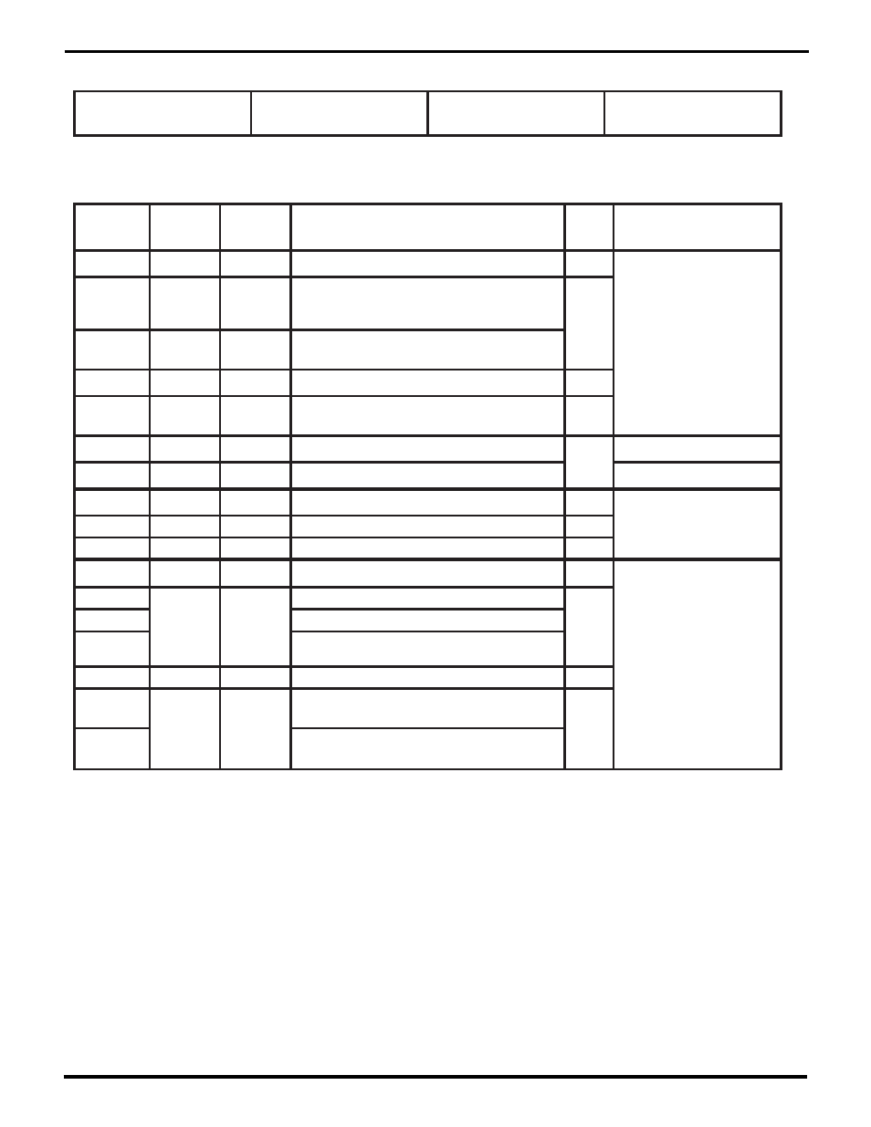
TxSubMode
Channel Mode Register (CMR)
Register Address 0 b 00001
TxMode
RxSubMode
RxMode
Bit(s)
Field/Bit
Name
Conditions
/Context
Description
RW
Status
Ref Chapter: Section
CMR11-8
Because the content of the SubMode fields depends on the Mode fields, the following descriptions are grouped by mode. TxSubMode
and RxSubMode bits that are not shown for a particular Mode value are Reserved in that mode and should be programmed with zeros.
TxMode
0000=Asynchronous
RW
5: Asynchronous Mode
CMR15-14
TxSubMode
00=send one stop bit; 01=two stop bits;
10=1 shaved stop bit (per CCR11-8);
11=2 shaved stop bits
RW
5: External Sync Mode
TxMode=0
CMR13-12
00=16 TxCLKs/Tx bit; 01=32 TxCLKs/Tx bit;
10=64 TxCLKs/Tx bit
CMR3-0
RxMode
0000=Asynchronous
RW
CMR5-4
RxSubMode
00=16 RxCLKs/Rx bit; 01=32 RxCLKs/Rx bit;
10=64 RxCLKs/Rx bit
RW
RxMode=0
CMR11-8
TxMode
0001=Reserved
RW
CMR3-0
RxMode
0001=External Sync
5: Isochronous Mode
CMR11-8
TxMode
0010=Isochronous
RW
CMR14
TxSubMode
0=send one stop bit; 1=two stop bits
RW
TxMode=2
CMR14
TxSubMode
0=send one stop bit; 1=two stop bits
TxMode=2
CMR3-0
RxMode
0010=2=Isochronous
RW
CMR11-8
TxMode
RW
0100=4=Monosync
5: Monosync and Bisync
Modes
CMR15
TxSubMode
RW
1=send CRC on Tx Underrun
TxMode=4
CMR13
1=send Preamble before opening Sync
CMR12
0=send 8-bit Syncs;
1=send Syncs per TxLength
CMR3-0
RxMode
RW
0100=4=Monosync
CMR5
RxSubMode
RW
RxMode=4
0=strip received Syncs;
0=include them in RxFIFO and CRC calculation
CMR4
0=expect 8-bit Syncs;
1=expect Syncs per RxLength
RW = Read/Write, RO = Read Only, WO = Write Only – for other codes see p. 8-10.
UM009402-0201