Analog Way Eikos LE - EKS400 Programmer's Guide User Manual
Page 8
8
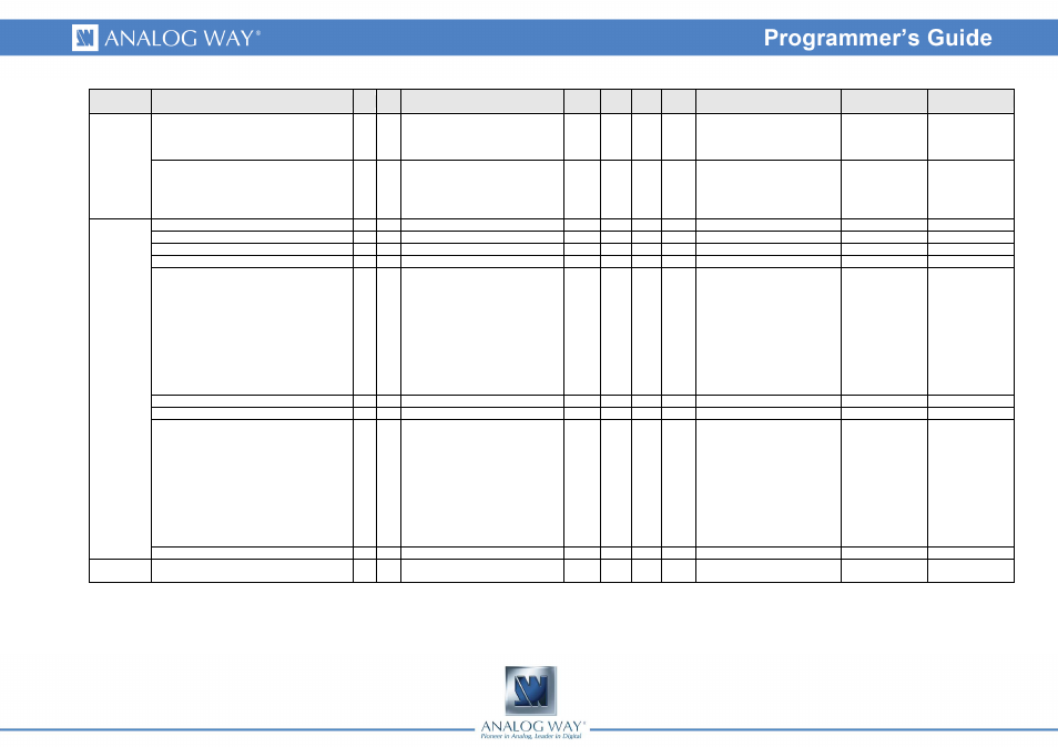
Group
Name
Cmd RespDescription
Read /
Write
Min
Value
Max
value
Default
value
Values
Index #1
Index #2
STDBYPROJ_RATE
wR wR Output display device UART speed Rd/Wr 0
3
2
0 = 1200bauds
1 = 2400bauds
2 = 9600bauds
3 = 19200bauds
STDBYPROJ_CTRL
wC wC
Rd/Wr 0
4
0
0 = No request
1 = Wake up request
2 = Standby request
3 = Clear Wake up message
4 = Clear standby message
VERSION
VERI1
xi
xi
Byte 0 and 1 of the device ID
Rd
0
65535 0
ex : AAAA
VERI2
xj
xj
Byte 2 and 3 of the device ID
Rd
0
65535 0
ex : AAAA
VERI3
xk
xk
Byte 4 and 5 of the device ID
Rd
0
65535 0
ex : AAAA
VERI4
xl
xl
Byte 6 and 7 of the device ID
Rd
0
65535 0
ex : AAAA
VERK
xK xK
Checksum/version of the
programmable components
Rd/Wr 0
65535 0
0 = Number of
programmables
components
1 = Main micro-
controler
2 = Front panel
micro-controler
3 = FPGA Caecina
4 = FPGA Fannia
5 = FPGA Thrasea
6 = Synchro CPLD
VERV
xV xV
Variable set version
Rd
0
65535 42
VERUPD
xU xU
Updater version
Rd
0
65535 0
OPT
yo
yo
Detected options
Rd
0
65535 0
bit 0 = Lan Module
bit 1 = SDI In 1 board (SDI 1
and 2)
bit 2 = Recording board
bit 3 = CF Caecina
bit 4 = CF Fannia
bit 5 = CF Thrasea
bit 6 = SDI In 2 board (SDI 3
and 4)
bit 7 = Audio Evolution
bit 8 = HDCP DVI In Evolution
REV
xR xR
Moher board revision
Rd
0
255
0
INPUT
IN_AUTOSET_ALL
Ia
Ia
Auto-setting request for all the
inputs
Rd/Wr 0
1
0