Table 6-30, Uart interrupt priorities, Table 6-31 – Artesyn ATCA-7365 Installation and Use (November 2014) User Manual
Page 183: Interrupt identification register (iir), Maps and registers, 4 interrupt identification register (iiir)
Maps and Registers
ATCA-7365 Installation and Use (6806800K65N)
183
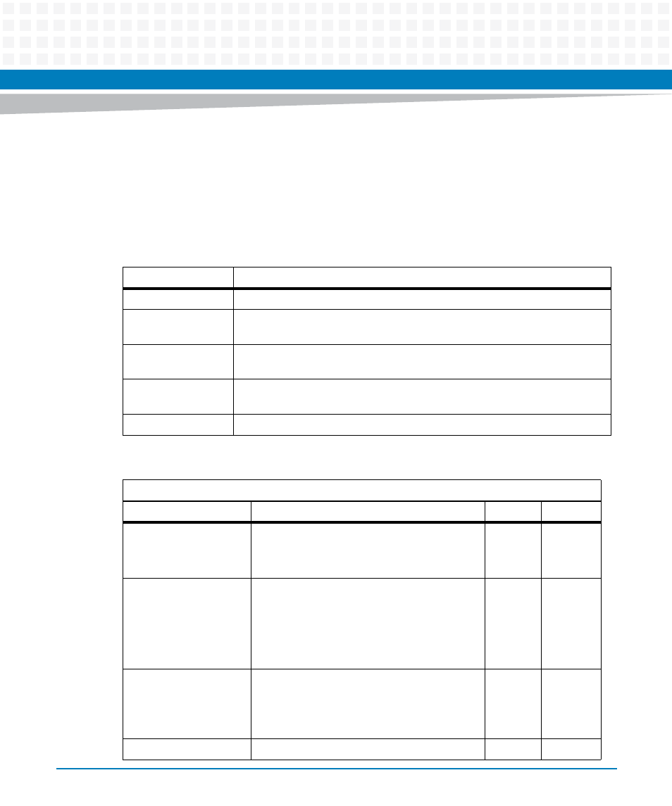
6.3.4.2.4 Interrupt Identification Register (IIIR)
In order to minimize software overhead during data character transfers, the UART prioritizes
interrupts into four levels (listed in
) and records these in the Interrupt Identification
Register. The Interrupt Identification Register (IIR) stores information indicating that a
prioritized interrupt is pending and the source of that interrupt.
Table 6-30 UART Interrupt Priorities
Priority Level
Interrupt Source
1 (highest)
Receiver Line Status. One or more error bits were set.
2
Received Data is available. In FIFO mode, trigger level was reached; in non-
FIFO mode, RBR has data.
2
Receiver Time out occurred. It happens in FIFO mode only, when there is data
in the receive FIFO but no activity for a time period.
3
Transmitter requests data. In FIFO mode, the transmit FIFO is half or more
than half empty; in non-FIFO mode, THR is read already
4
Modem Status: One or more of the modem input signals has changed state
Table 6-31 Interrupt Identification Register (IIR)
LPC IO Address: Base + 1
Bit
Description
Default
Access
0
Interrupt status bit:
1: no interrupt pending
0: interrupt pending
1
LPC: r
2:1
Interrupt priority level and source:
11: Receiver line status
10: Receiver data available
01: Transmitter holding register empty
00: Modem status
0
LPC: r
3
Time Out Detected:
0: No time out interrupt is pending
1: Character time-out indication (FIFO mode
only)
0
LPC: r
5:4
Reserved
0
LPC: r