Table 6-33, Line control register (lcr), Maps and registers – Artesyn ATCA-7365 Installation and Use (November 2014) User Manual
Page 185
Maps and Registers
ATCA-7365 Installation and Use (6806800K65N)
185
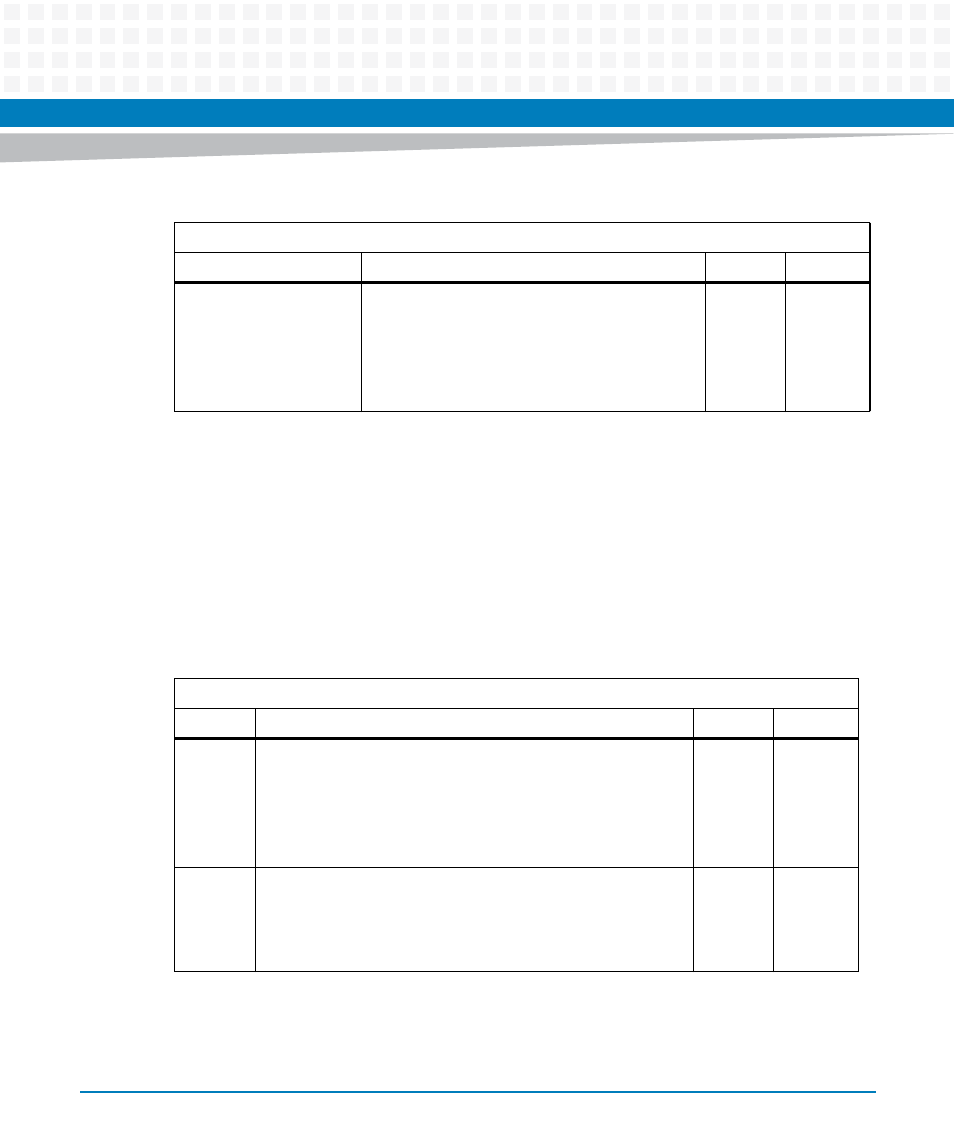
6.3.4.2.6 Line Control Register (LCR)
In the Line Control Register (LCR), the system programmer specifies the format of the
asynchronous data communications exchange. The serial data format consists of a start bit
(logic 0), five to eight data bits, an optional parity bit, and one or two stop bits (logic 1). The
LCR has bits for accessing the Divisor Latch and causing a break condition. The programmer can
also read the contents of the Line Control Register. The read capability simplifies system
programming and eliminates the need for separate storage in system memory.
7:6
Receiver FIFO interrupt trigger level:
00: 1 byte
01: 4 bytes
10: 8 bytes
11: 14 bytes
0
LPC: w
Table 6-32 FIFO Control Register (FCR) (continued)
LPC IO Address: Base + 2
Bit
Description
Default
Access
Table 6-33 Line Control Register (LCR)
LPC IO Address: Base + 3
Bit
Description
Default
Access
1:0
Serial character WORD length:
00: 5 bits
01: 6 bits
10: 7 bits
11: 8 bits
0
LPC: r/w
2
Stop bit length:
1: 1.5 stop bits for 5 bit WORD length
1: 2 stop bits for 6, 7, and 8 bit WORD length
0: 1 stop bit for any serial character WORD length
0
LPC: r/w