Fireplace installation – Avalon Firestyles Hideaway E Fireplace User Manual
Page 6
© 2010 Travis Industries Inc.
100-01
183_000
Fireplace Installation
The 21E Electric Fireplace may be installed into a variety
of settings. To install the fireplace assembly into a mantel,
refer to mantel assembly instructions.
! NOTE 1: A 15 Amp, 120 Volt circuit is required. A
dedicated circuit is preferred but not essential in all
cases. A dedicated circuit will be required if, after
installation, the circuit breaker trips or fuse blows on a
regular basis when the heater is operating. Additional
appliances on the same circuit may exceed the current
rating of the circuit breaker.
! IMPORTANT: If not using a mantel, the fireplace must
be installed in an enclosure with the following MINIMUM
internal/opening dimensions (Figure 5).
place a one-piece, solid, flat surface under the fireplace
insert.
Option #2: Hard wired.
1. Wire a dedicated, properly fused circuit with a 120 Volt,
15 Amp rating. Allow up to eight (8) feet (2.44 m)
of service cable for connecting the power supply to
the junction box for the fireplace when installing after
finishing wall.
CAUTION: Use two conductor, non-metallic sheath
cable with ground wire (3 wires total) for the incoming
power supply on fireplace inserts. Use appropriate wire
to meet local and national electrical codes for rated
power consumption.
2. Remove the outer jacket and strip the individual
conductor from the end.
3. Loosen the screw securing the junction box cover and
remove the cover.
4. Take the cables out from the junction box, loosen the two
wire twist nuts and remove the cord set (Figure 6).
Figure 6
5. Route the power supply wire through the knockout on
supplied alternative junction box cover and secure with a
wire clamp (not supplied) (Figure 7).
6. Connect the black wire (live) from the unit to the black
wire from power supply (Figure 7).
7. Connect the white wire (neutral) from the unit to the
white wire from power supply (Figure 7).
8. Connect the green wire (ground) from the unit to the
green wire from power supply (Figure 7).
9. Place all connectors inside the unit and secure the
junction box cover to unit. Ensure that the cable clamp
grips only the jacket of service cable.
Figure 5
34 ¼”
(870 mm)
10”
(2
54 mm)
20 ½”
(520 mm)
> 57” (1.44 m)
!
IMPORTANT:
There must
be a minimum
clearance of 57
inches (1.44 m)
from a ceiling
to the bottom of
the unit.
6
New Wall Construction
1. Select a suitable location that is not susceptible to
moisture and is away from drapes, furniture and high
traffic.
2. Place the fireplace in the desired location to see how it
will look in the room.
3. Mark the desired location on the floor and store the
fireplace in a safe, dry and dust free location.
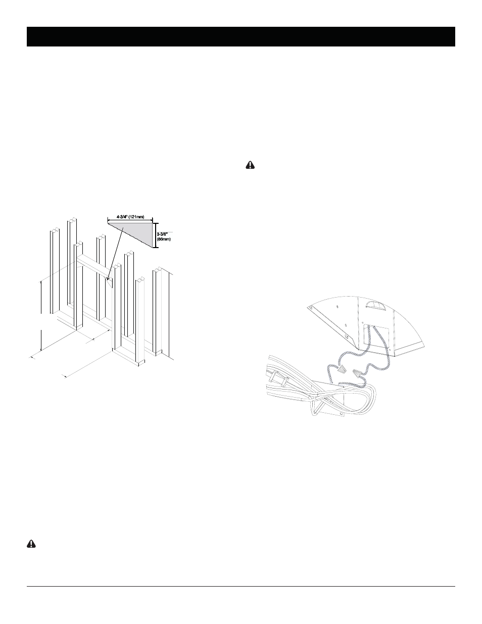
4. Use studs to frame an opening of 20 ½ inch (520 mm)
wide x 34 ¼ inch (870 mm) high x
10 inch (254 mm)
deep (Figure 5).
Install the upper corner framing supports.
Option #1: The power cord can be lead from behind the
trim and along the wall to an outlet near the fireplace.
CAUTION: Do not install the fireplace insert directly
on carpet or similar surfaces which may restrict air
circulation. If installing the fireplace in a carpeted area,