Installation, Cb a, Surround panel installation (continued) – Avalon Firestyles DVS Insert EF-2001 to 2005 User Manual
Page 14: For qualified installers only) © travis industries
1 4
Installation
(for qualified installers only)
© Travis Industries
4041213
1 0 0 - 0 1 1 5 0
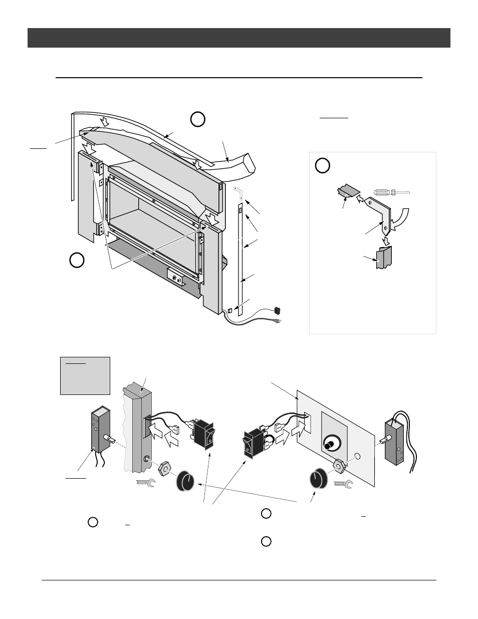
Surround Panel Installation (continued)
2
Install the top panel (arched or rectangular), insulation, and trim.
Install the top panel so
the two tabs insert into
the slots on the side
panels.
Top
Panel
Top Trim
"L" Bracket
Double-Back
Tape
Right Side Trim
Construct the panel trim. Insert one leg of
each "L" bracket into the top and side trim
piece. Align the trim to form a precise corner,
then tighten the two set screws with a small
standard screwdriver. Slide the trim over the
panels. Attach a piece of included double-
back tape to the bottom of each side trim to
keep it from flaring at the bottom.
Tighten the set screws from the
back side with a small standard
screwdriver
"L" Bracket
Right Side
Trim
Top Trim
c
b
a
Slot for on/off
switch
(rectangular or
arched)
Tuck the included insulation between
the top panel and the facing below
the rheostat (not along the sides).
Cut off excess insulation.
WARNING: The insulation must be installed along
the top of the insert and should cover or be below
the rheostat (to protect it from heat). Failure to
install the insulation will invalidate facing and
mantel clearances, creating a fire hazard.
NOTE:
On arched
panels make
sure these
stand-offs are
perpendicular
and not bent
over or
flattened.
3
Follow the directions below to install the on/off switch and rheostat (both are included with the insert).
b
c
a
Disconnect the on/off switch from the red and brown wires leading from
the heater. Insert the switch into the hole in the upper right of the
panel trim or control panel until it locks in place. Re-attach the red and
brown wires (orientation does not matter).
WARNING:
Make sure the heater
is unpluged before
installing the rheostat.
Control Panel
(next to gas control valve)
PILOT
IGNITER
Upper Right of Trim
(preferred)
Remove the knob and press nut from the rheostat. Insert the rheostat
into the hole in the upper right of the panel trim or control panel.
Secure the the press nut. Replace the knob.
11/16" Wrench
11/16" Wrench
Make sure the wires do not contact the burner pan or
other hot surfaces (secure with lock ties if necessary).
WARNING: Make sure
the insulation covers or
is below the rheostat.