Avery Dennison SNAP 500 User Manual
Page 60
60
User’s Manual—SNAP™ 500 Gen 1 and Gen 2
retaining screw in the assembly so you will have a place to lift the outboard
end of the assembly.
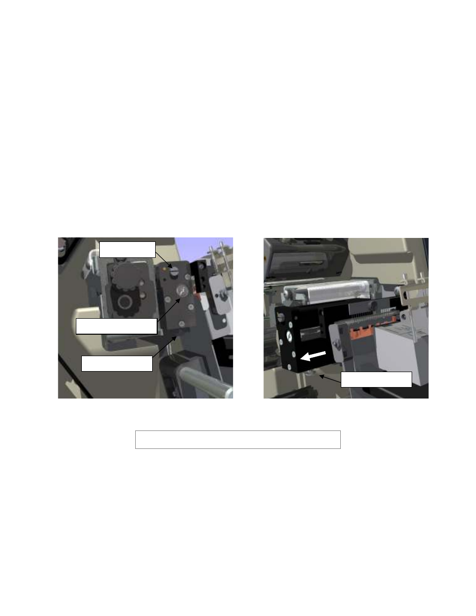
4. Place your right index finger on the head of the retaining screw and your
thumb on top of the assembly and lift up. This will remove the key that is
machined into the knife base from the groove in the mounting bracket (see
Fig. 18b).
5. Slide the knife straight out until the stripper contacts the outer support. This
will pull the rotary knife shaft from the motor drive coupler and the mounting
screw out of the clamp slot.
6. Lift the knife assembly vertically from the printer.
7. Remove the retaining screw from the used knife assembly and insert it into
the new knife assembly.
Figure 18b. Outboard End View of Knife
Figure 18c. Removing Knife Assembly
WARNING: Keep your fingers out of the knife assembly to
avoid personal injury.
8. Properly dispose of the used knife assembly.
9. To insert the new knife assembly, slide it down vertically into the space
between the Auxiliary Feed and the Nip Rollers.
10. Hold the knife assembly on the upper outboard corner. Use a flat blade
screwdriver to rotate the rotary knife blade with the screw slot in the knife
until the knife blade slips into the drive shaft.
11. Continue to hold the knife assembly in place. Use a Phillip’s head
screwdriver to retighten the screw.
Pivot Screw
Knife Shaft Rotation
Retaining Screw
Retaining Screw