Input sensing, Alarms and outputs – Basler Electric BE1-59NC User Manual
Page 10
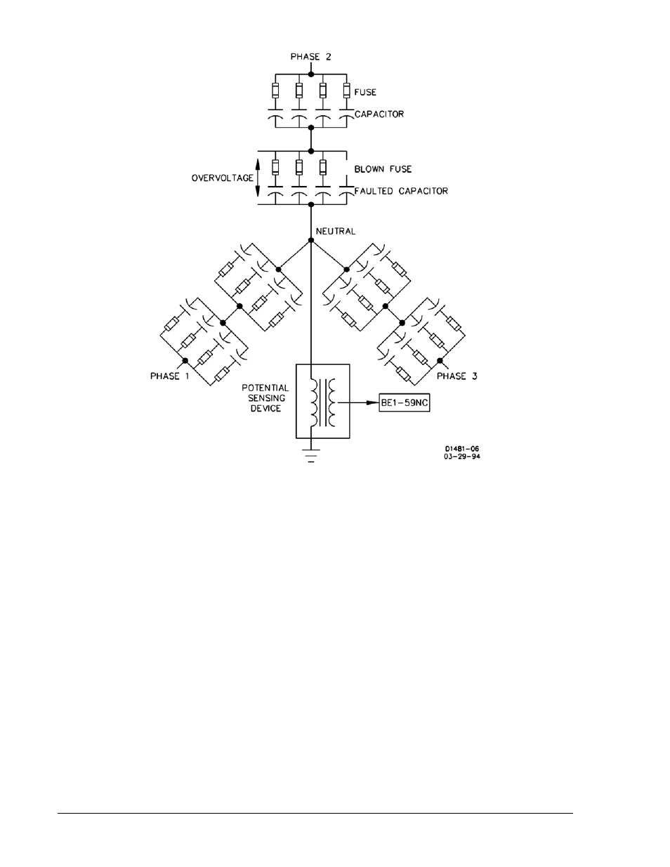
Figure 1-1. Ungrounded 3-Phase, 3-Wire System
Input Sensing
BE1-59NC Neutral Overvoltage relays receive the input signal from voltage sensing devices connected
between the capacitor bank neutral and ground. These voltage sensing devices can be potential
transformers or resistor potential devices. Ideally, the voltage across each leg of a capacitor bank is
balanced, and the voltage from neutral to ground is zero. If a single capacitor fails and blows the
protecting fuse, an unbalanced condition occurs that shifts the neutral and creates a small but
measurable voltage. Through the potential sensing devices, the neutral relay senses this voltage
unbalance and reacts to give the appropriate signal (usually an alarm or trip depending on the voltage
level).
Further loss of more capacitors increases the neutral voltage. The relay senses this voltage increase, and
reacts to give the appropriate signal. This signal is usually a trip depending on the voltage levels and how
the protection scheme is designed.
Alarms and Outputs
Sensitive settings on the relay are used as an alarm to alert that a fuse has blown and maintenance is
required. They would be typically set at a level corresponding to the voltage rise caused by one blown
fuse. The second output would have a setting that would be set to trip the capacitor bank off the bus or
line when the voltage exceeds 110% of the nominal capacitor bank voltage. This setting depends on the
capacitor bank size and configuration.
1-2
BE1-59NC General Information
9279400990 Rev D