Functional description, Introduction, Inputs – Basler Electric BE1-59NC User Manual
Page 19: Filters, Overvoltage comparator, Definite time delay, Section 3, Functional description -1
SECTION 3
• FUNCTIONAL DESCRIPTION
INTRODUCTION
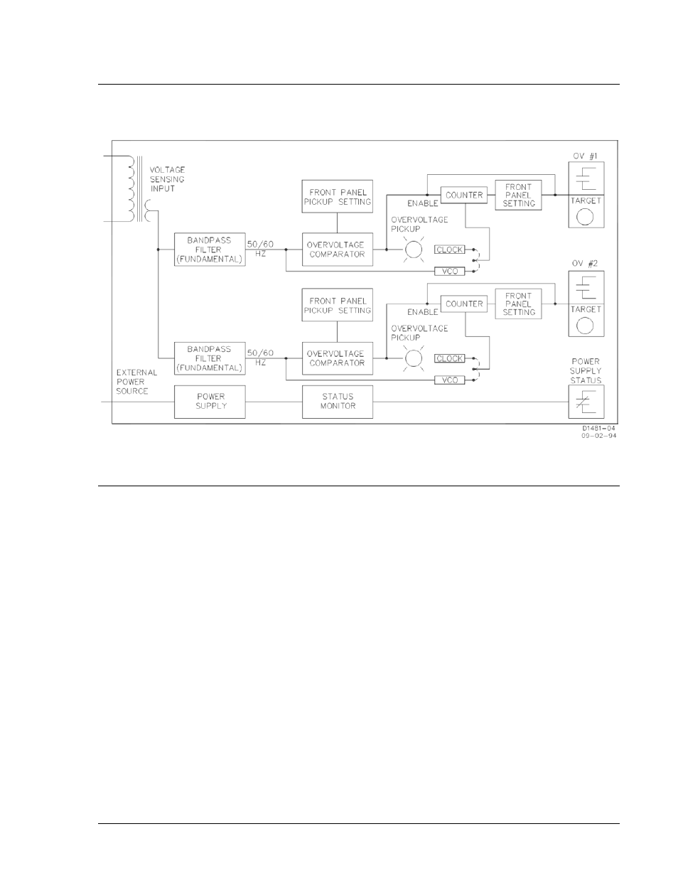
BE1-59NC relay functions are illustrated in Figure 3-1 and described in the following paragraphs.
Figure 3-1. Function Block Diagram
FUNCTIONAL DESCRIPTION
Inputs
Sensed voltage developed across the input sensing device connected in the neutral-grounding current
transformer secondary is applied to the BE1-59NC Neutral Overvoltage Relay. Internal transformers
provide further isolation and step down for the relay logic circuits. BE1-59NC Neutral Overvoltage Relays
may also be used in ungrounded systems with voltage transformers connected in wye/broken delta
configurations. Typical connection methods are shown in Section 4. Overvoltage #1 and Overvoltage #2
circuits are functionally the same except for timing characteristics.
Filters
Bandpass filters provide peak sensitivity at 50 or 60 hertz for the overvoltage #1 and overvoltage #2
inputs. Third harmonic rejection is 40 dB minimum.
Overvoltage Comparator
Each overvoltage comparator circuit receives a sensing voltage from the bandpass filter and a reference
voltage from the front panel setting. When the input exceeds the setting reference, the comparator output
enables the timing circuit and the OVERVOLTAGE PICKUP LED turns ON.
Definite Time Delay
An output signal from the comparator circuit enables a counting circuit to be incremented by an internal
clock. When the counting circuit reaches the count that matches the number entered on the TIME DIAL,
the output relay and auxiliary relay are energized. However, if the sensed input voltage falls below the
pickup setting before the timer completes its cycle, the timer resets within 2.0 cycles.
9279400990 Rev D
BE1-59NC Functional Description
3-1