Ethernet, Thernet – BrightSign HD2000 Hardware Guide User Manual
Page 7
BrightSign HD2000
This information applies to a product under development. Its characteristics and specifications are subject to change without notice. Roku assumes no
obligation regarding future manufacturing unless otherwise agreed to in writing.
www.rokulabs.com
© Roku 2006
19
Button 8 input
20
Button 7 input
21
Ground
22
Button 4 input
23
Button 2 input
24
Ground
25
Button 0 input
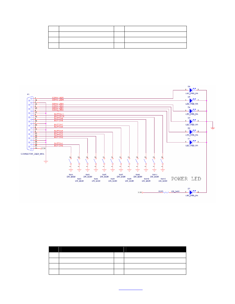
The following Diagram shows how to wire up a button and LED to each input/output (this is the
schematic of the Roku button/led board that we sell for development use). You of course can use as little
or as many of the inputs and outputs as you wish.
Ethernet
The HD2000 has a standard RJ45 connector for 10/100 base T Ethernet. The pinout of the RJ45 is as
follows (NOTE: This pinout is only accurate for REVC and later HD2000 boards, REVB has a hardware
bug in this pinout):
pin Description
pin Description
1
TX+
2
TX-
3
RX+
4
RC to ground
5
RC to ground
6
RX
7
RC to ground
8
RC to ground