Setup and operation – BUG-O Systems CWP-11 User Manual
Page 8
8
WIRE SPEED AND VOLTAGE ADJUSTMENT
The wire speed control on the front of the CWO-3535
Wire Feed Control box has a dial that is calibrated
directly in inches per minute. Set the voltage using the
control on the power source.
MACHINE CONTROLS
Operational parameters can be set using the two con-
trol boxes. Please refer to the sections in this manual
entitled “Rotation Controls” and “Pendant Control” for
descriptions of the various speed and directional capa-
bilities. For the LN-9 Wire Feed Control Box; refer to the
supplied LN-9 Semiautomatic Wire Feeder Manual from
Lincoln Electric.
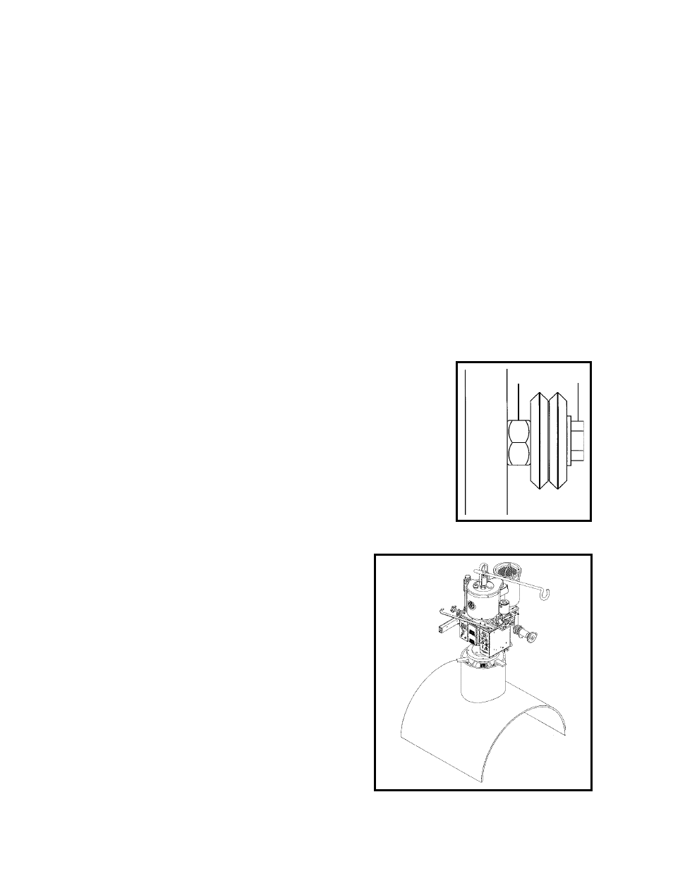
INSTALLATION
Use a 3-Jaw Chuck to mount and center the CWP-11
on nozzles with or without flanges, as seen in Figure 2.
See page 43 for a list of available 3-Jaw Chucks.
Figure 2: Installation with 3-Jaw Chuck
ADDITIONAL CABLES
Each circle welder is supplied with the following cables:
1. CWO-3971 50' (15 m) power cable that connects the power source to the cable
connector on the top gear of the machine.
2. CWO-3040 50' (15 m) weld cable that connects the lead coming out of the top of the ma-
chine to your power supply, using the quick connect connector .
3. CWO-9406 50' (15 m) gas shielding hose that connects the gas fitting on the top of the
shaft to your shielding gas supply. (MIG models only.)
WHEEL ADJUSTMENT
The CWP-11 Motorized Racking System (CBP-1640) and the Large
Horizontal Racker (CWO-1690) are equipped with adjustable wheels.
Always check these components for proper wheel adjustment before
using the machine. Adjust the wheels if you can cock or wiggle the
components out of alignment. The wheels should be snug but not
prohibit movement along the path of travel. The wheels with the hex
stand-offs (shown in Figure 1) are adjustable. To adjust the wheels,
loosen the hex bolt (A) until the eccentric bushing (B) can be rotated.
Correct the wheel alignment by rotating the eccentric bushing (B).
Once adjusted, hold the eccentric bushing (B) while tightening the
hex bolt (A). Recheck alignment.
A
B
SETUP AND OPERATION
POWER SOURCE
Use only constant voltage (CV) type power sources with this circle welder machine. If using a
multiple process power source, be sure that it is set for constant voltage (CV) output as per the
instructions in the manual for the power source. Set the power source polarity switch or properly
connect the electrodes and work leads for the correct electrode polarity.
GUNS AND CABLES
All circle welders come equipped with a gun and cable assembly. It is our recommendation that
at least once a week the liner be taken out of the cable and soaked overnight in a solvent solu-
tion. To keep the wire moving it is also recommended that a felt clip be saturated with a product
like Ferro Slick and fed through the incoming tube of the wire feeder at least once a day.
Figure 1: Adjustable Wheel