Introduction – BUG-O Systems DC IV v.2 User Manual
Page 4
4
The DC-IV Drive Unit has been factory tested and is ready to be mounted on
any standard BUG-O SYSTEMS carriage.
To install the drive unit, screw the cam clutch stud into the carriage. Use the
5/16 x 3/8 socket head shoulder screw provided to attach the DC-IV to the
carriage.
Rotate the
Cam Knob (B) to move the drive in and out of engagement with
the rack.
To lock the drive position, tighten the
1/4-28 Wing Nut (A) provided.
To position the drive unit, loosen the
1/4-28 Wing Nut (A) and turn the Cam
Knob (B) far enough to disengage the drive pinion from the rack. Move the
carriage to the starting point on the rail. Turn the
Cam Knob (B) to engage
the drive pinion with the rack. Retighten the
1/4-28 Wing Nut (A) to lock the
drive carriage into position.
Two pinion gears are provided. The
Factory Installed Pinion (H) engages
the bull gear to provide a high torque, low speed range. The user can easily
install the
Alternate Pinion (J) to bypass the bull gear and obtain a low
torque, high speed range.
Once the
Power Cord (C) is plugged into the appropriate power source, the
Pilot Light (D) will glow. Switch (E) controls the direction of travel, with the
center position as “OFF”.
Knob (F) controls the speed.
The
Circuit Breaker (G) protects the drive unit against overload or electrical
faults.
CAUTION: IF THE CIRCUIT BREAKER OPENS, FIND AND CORRECT
THE CAUSE OF FAILURE BEFORE RESETTING.
INTRODUCTION
The DC-IV Drive Unit is the basic drive for many BUG-0 SYSTEMS machines.
This drive unit mounts on BUG-0 carriages designed for DC drives. The
DC-IV is a positive rack and pinion drive with a wide range solid state speed
control. Once mounted on a carriage, the drive unit will run in any position
using Aluminum Rigid Rail, Aluminum Flex Rail or Bent Rigid Rail [with a
minimum radius of 10' (3 m)].
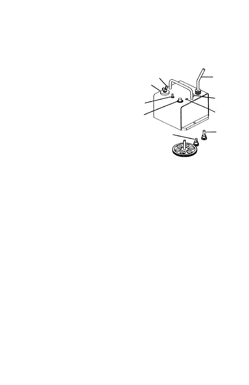
A. Wing Nut 1/4-28
B. Cam Clutch engages and disengages the drive
C. Power Cord
D. Power Indicator Light
E. Forward-Off-Reverse Switch
F. Infinitely Variable Speed Control
G. Circuit Breaker
H. Factory Installed Pinion provides a
high torque, low speed range
J. Alternate Pinion bypasses the bull gear
to obtain a low torque, high speed range
ASSEMBLY AND OPERATING INSTRUCTIONS
FEATURES:
B
A
E
F
H
J
D
G
C