22
8,12,21
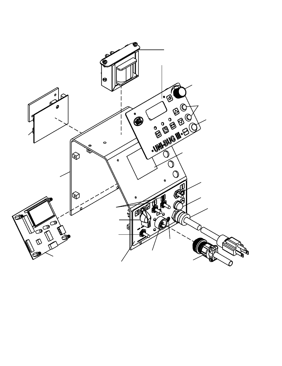
UNI-2410 COVER ASSEMBLY / EXPLODED VIEW
11,16,19,32
24
29
28
1,4
6,7
9,10,20
31,18,17,2
9,26,32
3
25
22,13
27
23,14
30
15,5
NOTE: See UNI-BUG III wiring diagram for voltage specific electrical components.
33