4 connecting the console frames, 1 audio bus connections, 2 pfl – Cadac C-Type User Manual
Page 10: 3 earth, 0v, gnd and frame connections, Connecting the console frames -4, 417 &rqqhfwlqj#wkh#frqvroh#iudphv, See also appendix a
1-4
Connecting the mixer systems
C-Type
Revision C2005-2
417
&RQQHFWLQJ#WKH#FRQVROH#IUDPHV
41714
$XGLR#%XV#&RQQHFWLRQV
If the console is used in a multi-frame configuration then the busses need to be con-
nected in a ‘daisy chain’ fashion.
Each end of a frame has six audio bus connectors
. The bus cables are simply linked between similar connectors on the
end of the nearest frame.
See also appendix A.
41715
3)/
Connect the supplied and identified cable between the PFL male XLR output
and the female XLR input on the next frame labelled Input to Headphones
jack sockets.
41716
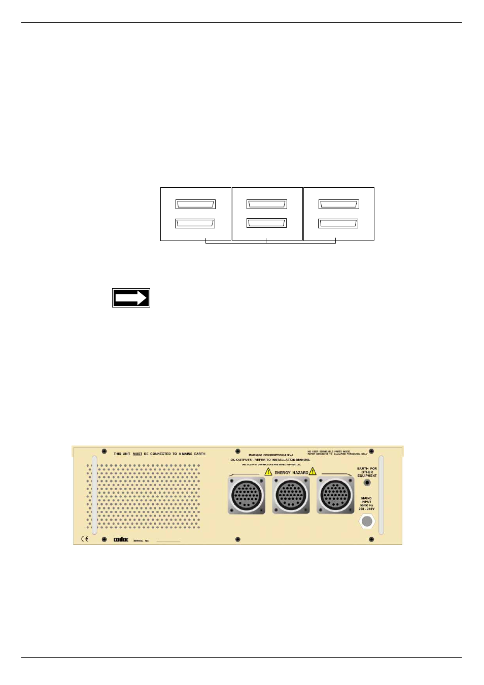
(DUWK/#39/#*1'#DQG#)UDPH#&RQQHFWLRQV
Figure 1-5 shows the rear panel of the power supply units in a single PSU system.
A 0V stud is provided on the back of the PSU for grounding external equipment.
In addition to the terminal on the back of the PSUs, there is an
0v connection on the
rear of each console frame. This connection is included for connecting external
equipment.
In addition to the terminal on the back of the PSUs, there are
0v, GND and FRAME
connections on the rear of each console frame. The shorting-bar link between the 0v,
$8',2#%86#)5$0(#72#)5$0(
$8',2#%86#)5$0(#72#)5$0(
4
5
6
7
/,1.#7+(6(#&211(&7256
72#7+(#$'-$&(17#&211(&7256
21#7+(#1(;7#)5$0(
FIG 1-4. Audio/Data Bus connections.
$8',2#%86#)5$0(#72#)5$0(
FIG 1-5. PSU 8400.