2 monitoring module 7912 - rear panel, Monitoring module 7912 - rear panel -7 – Cadac C-Type User Manual
Page 49
Advertising
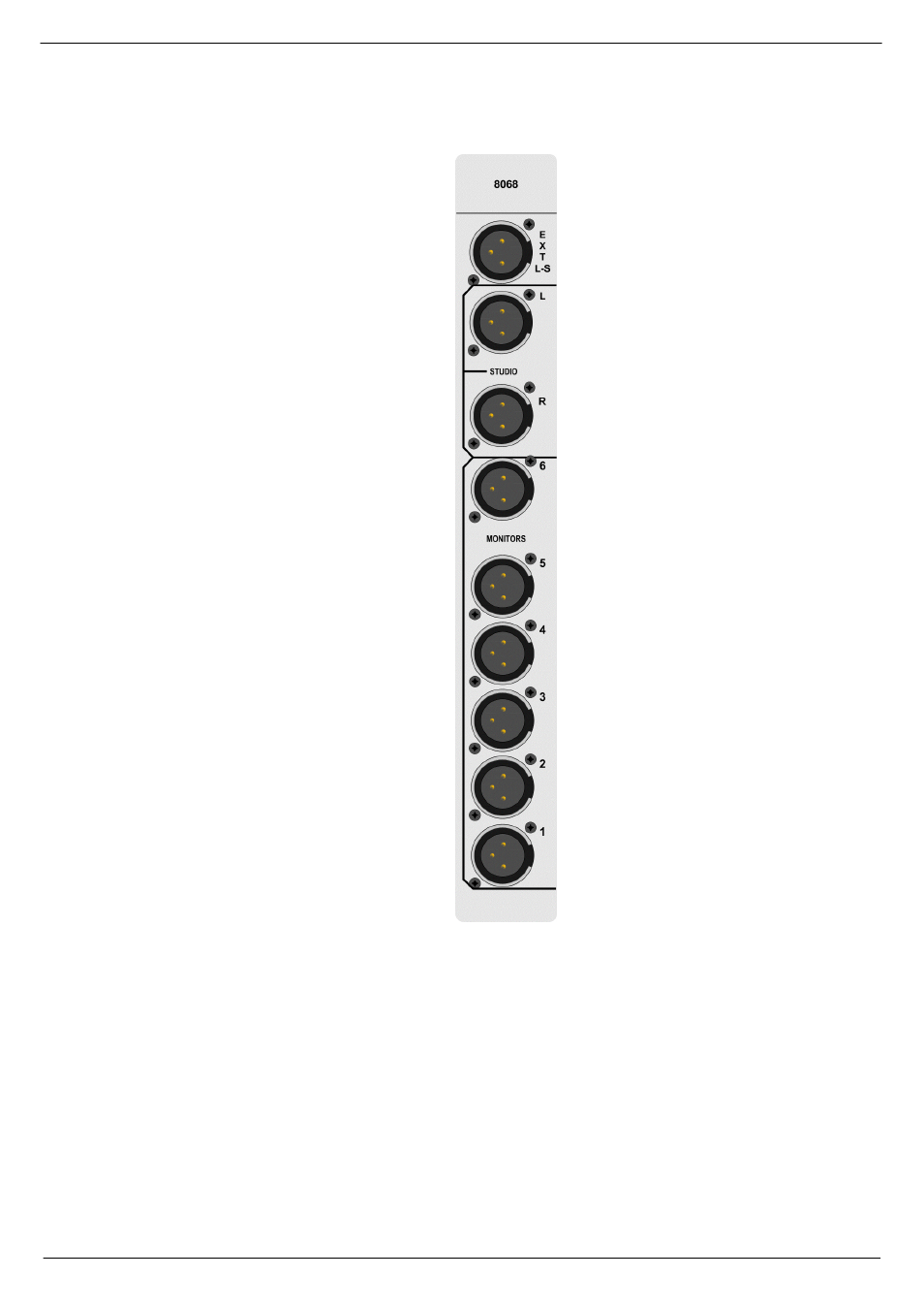
Monitoring Module 7912
6-7
Revision C2005-2
C-Type
915
0RQLWRULQJ#PRGXOH#:<45#0#UHDU#SDQHO
OUTPUT TO EXTERNAL SPEAKER FOR
MONITORING OR OF PFL OR RTB
LEFT OUTPUT - STUDIO MONITOR
RIGHT OUTPUT - STUDIO MONITOR
OUTPUT - RIGHT CHANNEL SURROUND
OUTPUT - LEFT CHANNEL SURROUND
OUTPUT - SUB-WOOFER
OUTPUT - CENTRE
OUTPUT - RIGHT
OUTPUT LEFT
Inputs and outputs are electronically
balanced and connected via 3-pin
XLRs and follow the wiring conven-
tion:
PIN 1 = Screen
PIN 2 = In-phase signal (hot)
PIN 3 = Out-of-phase
signal (cold)
IMPORTANT NOTE: Pin 1 on XLR
connectors and the ‘sleeve’ con-
nections on the jack sockets are
connected to the FRAME. This is
to ensure that the console can
comply with the Electric Compati-
bility (EMC) directive.
Advertising