Baud rate handshaking cx263 jumper settings, 9600 baud, Dig/an – Cloud Electronics CDI-S200 User Manual
Page 5: Fr/rem
CDI-S200 Installation Guide v1.0
5
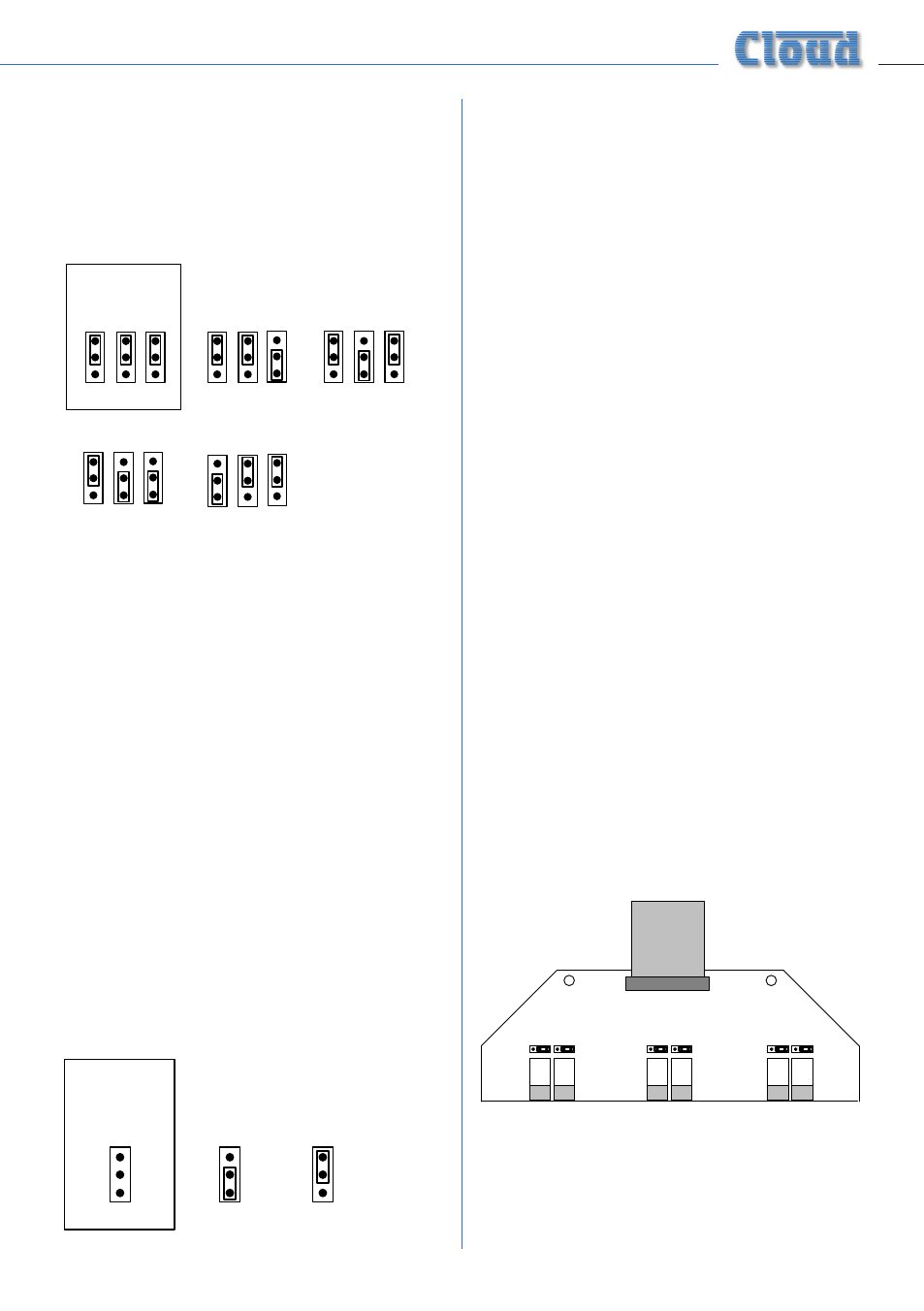
Baud Rate
Jumpers J1 to J3 set the serial port’s baud rate.
The default setting is
9600 baud
. Check the
baud rate of the controlling equipment. If a
different baud rate is required, set the jumpers
according to the diagram below:
DEFAULT
SETTING
9600 baud
J1 J2 J3
J1 J2 J3
J1 J2 J3
J1 J2 J3
J1 J2 J3
4800 baud
1200 baud
2400 baud
300 baud
Handshaking
RS-232C serial communication between
equipment sometimes requires flow control
(or “handshaking”), to confirm that transmitter
(the controller) and receiver (the CDI-S200
in this case) are correctly synchronised. PCB
jumper J4 controls handshaking.
Handshaking may be via “hardware”,
“software”, or off. Hardware handshaking
is also referred to as “RTS/CTS”, and needs
additional pins of the 9-pin serial connector
to be wired (see “Pinout” on page 8).
Software handshaking is also referred to as
“Xon/Xoff”.
The default setting is off (no handshaking); J4
is left attached to the centre pin of the header
at the factory. If the controlling equipment
requires handshaking, reset the jumper
according to the following diagram:
CX263 jumper settings
In order for the CDI-S200 to fully control
the CX263, it is necessary to correctly set
some jumpers on the CX263 main PCB. These
are J4 to J6, and J19 to J24. Because some of
these jumpers will be inaccessible once the
CDI-S200 PCB is installed, we recommend that
they are set before fitting it.
Jumpers J4 to J6 are all on 2-pin headers, and
can thus be present or absent. See page 6
for a guide to their location. They determine
how the CX263’s Mic Input 1 access control
operates. When a CDI-S200 PCB is installed, all
three jumpers must be absent (we recommend
that the jumpers are electrically removed, but
left in place on just one pin of the header, in
case the unit needs to be reconfigured in the
future).
To move the jumpers, use small pliers to gently
pull the jumper off the header pins and replace
in the correct position. Do not use undue
force, and do not use pliers which are too big.
Jumpers J19 to J24 determine how music
source selection and music level in each
zone are controlled remotely. To allow a
CDI-S200 PCB to fully control a CX263,
all six jumpers must be in the ‘SW’
position. These jumpers are all on the small
“daughter-board” at the centre-rear of the
CX263 which carries the
DIG/AN
and
FR/REM
switches for each zone.
It is possible to configure the CX263 so that
only certain unit functions are under the
control of the CDI-S200. Refer to “CX263
switch settings” on page 7 for more details.