Coloronix 6″ RGB Pathway Light User Manual
Page 10
1. Electrical Connection
Connect field supply wires (120VAC or 24DC—see specifications) to driver input power
leads using appropriately sized wire nuts. Hot to black, neutral to white, ground to
green and bare copper wire (if applicable).
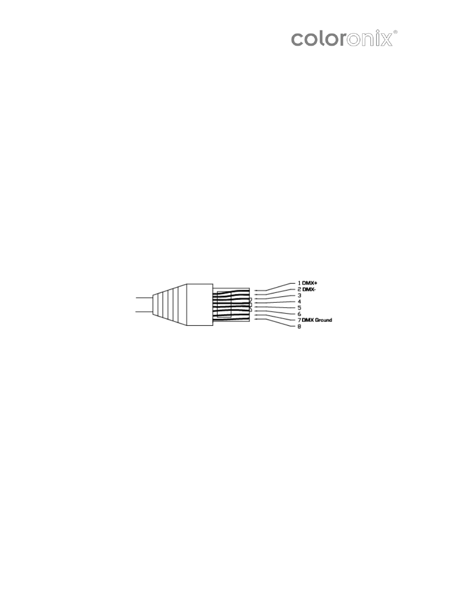
2. Data Connection
Connect data cables in series.
Fixtures on a serial data link must be daisy chained in one single line. To comply
with the EIA-485 standard, no more than 32 fixtures should be connected on one
data link. Connecting more than 32 fixtures on one serial data link without the use
of a DMX optically-isolated splitter may result in deterioration of the digital DMX
sig
For RJ45/CAT5 installation, a RJ45 jack can be used (use PCL004 RJ45 coupler).
nal.
Maximum recommended serial data link distance: 500 m (1640 ft)
Maximum recommended number of fixtures on a serial data link: 32
Notice: To comply with all local codes
technic
Notice: Communication cables and AC power lines must not be run in the same
accessories using DATA IN and DATA OUT.
B. In order that they may be easily accessed from the room once construction is
complete, secure data cables in the immediate proximity of the housings.
Coloronix strongly recommends clearly marking communication cables near the RJ45
connectors (or end of cables) in such a way to indicate the correct order of connection.
To avoid signal transmission problems and interference, it is always advisable to
and jurisdiction, qualified communications
ians must do communications wiring.
conduit.
A. Route Data Cables in series between housing and any communications
C. Use RJ45 DMX terminator, insert in “DATA OUT” of last fixture in series.
*
connect to a DMX signal terminator.
Page 10—Coloronix RGBW Pathway Lighting Manual V1.0