10 (config:) ref, 1 (config: ref) modem reference – Comtech EF Data CDM-760 User Manual
Page 132
Front Panel Operation
Revision 2
CDM-760 Advanced High-Speed Trunking Modem
MN-CDM760
6–46
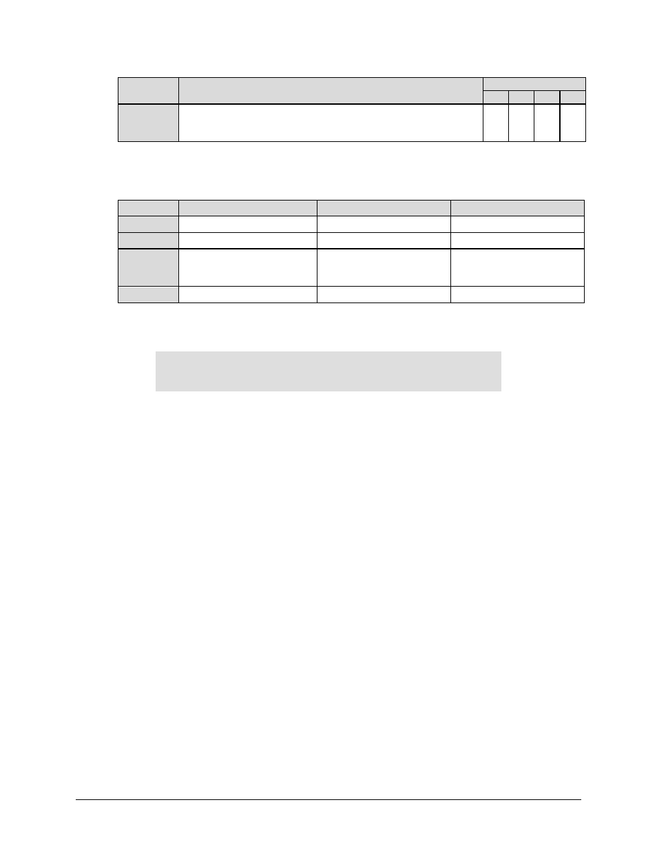
Selection
(Mask)
Description
Available Mask State
A
F
M F/T
EthLink
This indicates that an Ethernet Interface is selected using the CONFIG: Intf
menu (Sect. 6.2.2.4) as the active interface, but an Ethernet cable with
Ethernet traffic has not been detected on this physical port.
X X X X
For each mask selection, use the arrow keys to set the available mask state as noted in the
previous table. Press ENTER. Note the following:
Mask Type Unit Status LED Color
Fault State
Visible Location
Alarm
Amber
None
Monitor: Live Alarms menu
Fault
Red
J1 Alarm Connector
Monitor: Stored-Events log
Mask
None
None
None: A masked event is not
logged and is not seen in
any menu.
Fault-Tx On Red
J1 Alarm Connector
Monitor: Stored-Events log
6.2.2.10 (CONFIG:) Ref
Modem Reference: Internal
Internal Ref Fine Adjust:-001
()
Use the arrows keys to select Modem Reference or Internal Ref Fine Adjust. Press ENTER.
6.2.2.10.1 (CONFIG: Ref) Modem Reference
Use the
arrow keys to select a parameter. Press ENTER.
Note the following:
•
Select Internal mode to frequency-lock the modem to the high stability ±0.06 ppm 10 MHz
internal oscillator.
•
Select Internal+O/P (Internal with Output) mode to use the 10 MHz internal reference an
output on the rear panel J8 | EXT REF BNC connector. This mode is useful when you desire
to use a single frequency reference for both the modem and another piece of equipment in
the system. When selecting this mode, a green LED adjacent to the connector illuminates to
alert you that the connector, normally used as input, now has an output signal present.
•
Select the Ext 1 MHz, Ext 2 MHz, Ext 5 MHz, or Ext 10 MHz mode to frequency-lock the
modem to an injected external reference on the rear panel J8 | EXT REF BNC connector.