3 initial system setup and verification – Comtech EF Data PCB-4000 User Manual
Page 33
PCB-4000 1+1 Phase Combiner
Revision 2
Installation, Startup, and Troubleshooting Procedures
MN/PCB4000.IOM
3–5
3.3
Initial System Setup and Verification
This section assumes that the system has been assembled, that all cables have been connected,
and that the output port is terminated in a broadband high power load as depicted in the Figure
1‐2 block diagram in Chapter 1. INTRODUCTION. If the system is “live” and you desire only to
verify operation, see Section 3.5.
You may verfiy overall system performance by measuring the ratio of the transmitted power to
that of the power being dissipated by the “dummy” load. Adjust the gain and amplitude balance
if necessary.
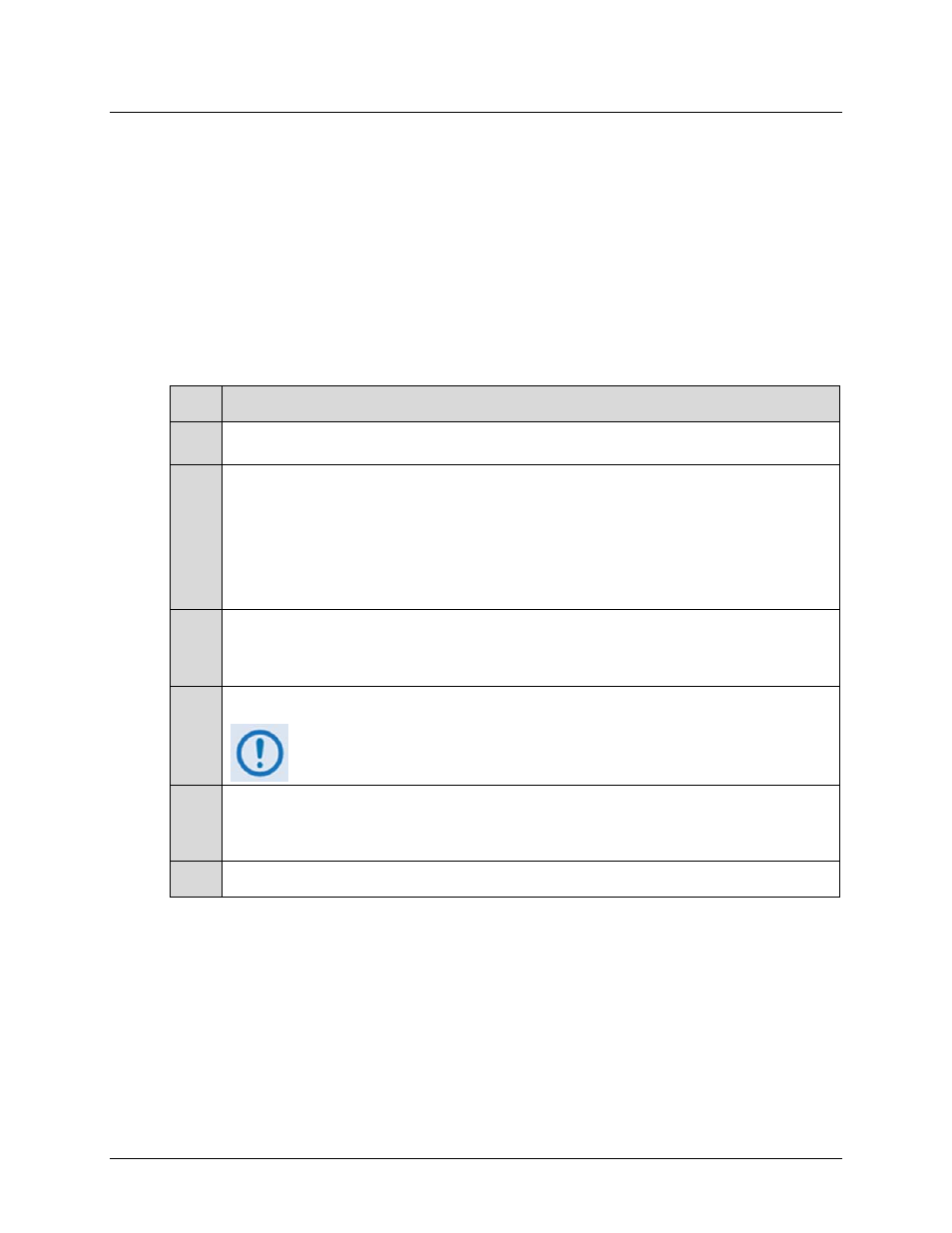
Follow these steps:
Step Task
1
In the normal 1+1 phase combiner mode, the RED=X remote command setting should be set to “1”. You can
verify this by querying the system (see Chapter 5. SERIAL REMOTE CONTROL).
2
A. Attach a power meter to the Combined Output Power Test Coupler (Figure 3-1).
B. Apply a low-level signal at center frequency; making sure the output signal (at the system output port –not
the coupled port) will be at least 10 dB below Prated.
C.
Measure the output power and include the coupler correction factor.
3
A. Attach a power meter to the Wasted (“Load”) Power Test Coupler (Figure 3-1).
B. Measure the power and include coupler correction factor.
4
If the Wasted (“Load”) power level is 15-20 dB below the transmitted power, the system is operating correctly.
If the ratio is below 10 dB, proceed to the gain and phase alignment
procedures that follow in this chapter.
5
A. Slowly increase the input power until the desired operating output power is achieved.
B. Again, verify the appropriate ratio of the transmitted to dissipated power.
6
If desired, repeat Steps 1 through 5 at different frequencies to verify proper full bandwidth operation.