3 digit segmentation, 4 schematic, 5 troubleshooting – Daktronics CH-1018V User Manual
Page 20: Digit segmentation -2, Schematic -2, Troubleshooting -2
Maintenance &
Troubleshooting
3-2
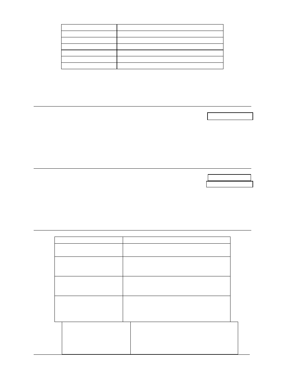
Connector Number
Function
1-16
Outputs to digits
17 Signal
Input
18
Power input for outputs 1-8 (120 V)
19
Power input for driver logic and fan (120V)
20
Power input for outputs 9-16 (120V)
24
Dim option selector
In Drawing A-55700, the numbers on the digits refer to the lamp driver output connector
wired to each digit.
3.3 Digit
Segmentation
Reference Drawing: Segments, 4x7 Lamp Matrix Digit.................. Drawing A-37685
In a digit certain lamp always go on and off together. These groupings of lamps are known as
"segments". Each digit has eight segments, referred by letters A through H. Drawing A-
37685 illustrates these segments and shows which connector pin and wire color is wired to
each segment.
3.4 Schematic
Reference Drawings: Driver Enclosure, Power & Signal ............... Drawing A-37915
Schematic, Pwr & Sig, 1421-H.................... Drawing A-38788
The schematic diagram in Drawing A-38788 shows the power and signal inputs into the
display and to the lamp driver. The component numbers correspond to those shown in
Drawing A-37915.
3.5
Troubleshooting
Observed Problem
Possible Cause
One lamp won’t light
• Burned-out lamp
• Broken wire behind digit
Digit segment won’t light
• Broken wire
• Poor contact at driver connector
• Internal driver malfunction
Entire digit won’t light
• Broken wire (black)
• Poor contact at connector, pin 7
• Fuse blown in driver
Half the display won’t light
• Service breaker tripped
• Main fuse blown
• Poor contact at main power connection
• P18 disconnected
Entire display won’t light
• Power disruptions
• Poor signal connection
• Driver logic fuse blown
• Control not connected to display
• P20 disconnected