01 theory of operation – Daktronics S SERIES User Manual
Page 5
1
T
HEORY OF OPERATION
Each Vortek hoist is connected to the main high voltage power buss through a safety twist-
locking plug. This plug brings in the main 208 or 480 VAC (refer to system riser), 3-phase
power that is connected to the motor contactors and motor brake located in each hoist
assembly. The high voltage power originates in the Master Control Cabinet (MCC). Also
connected to each Vortek hoist assembly through a safety locking connector are 24-volt DC
control and E-Stop circuit.
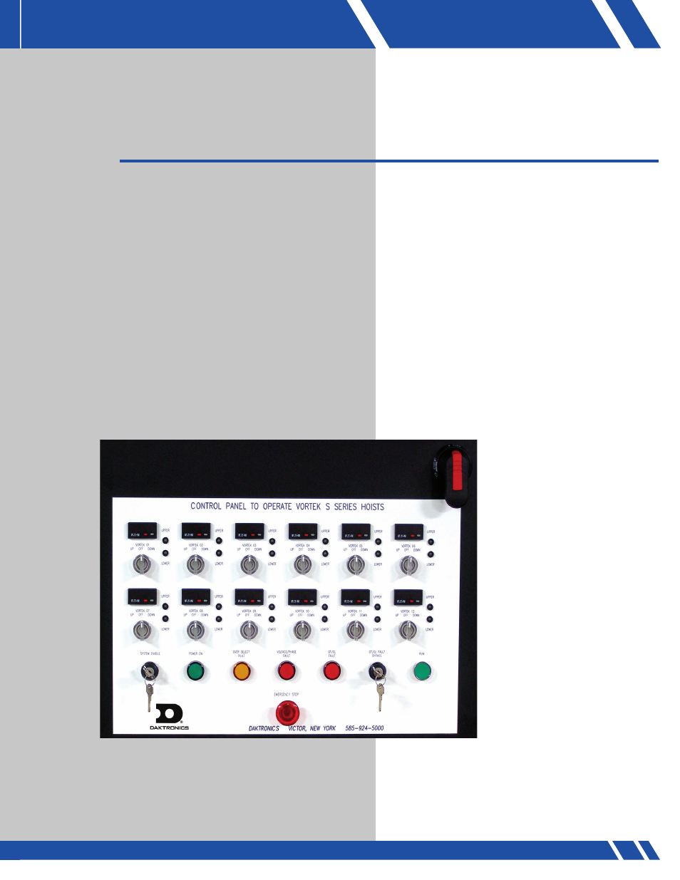
The reversing contactors control all movements of the hoist. Each S Series controlled
hoist with Push Button Control runs in open loop and is controlled at the main MCC via
momentary push buttons. Each hoist is protected via hardwired UP and DOWN control
signals, hard struck limit switches, emergency stop status and optional over/under capacity
sensors. The UP and DOWN control signals determine which contactor to energize for
direction to run the hoist (Figure 1). The limit switches are used for maximum up and
down travel. The emergency STOP status is used to detect the operation of the emergency
stop system and the
optional over/under
capacity sensors will
ensure that the hoist is
being operated within its
designed capacity.
Housed within the MCC
is a 24-volt DC power
supply that powers the
control circuit and the
E-Stop circuit. A fused
disconnect and a master
control contactor are also
mounted inside the MCC.
The 24-volt DC E-Stop
circuit is connected to the
E-STOP button located
on the front of the master
control cabinet as well as
the E-STOP button located
on the pendant, if
applicable.
01
THEORY OF OPERATION
FIGURE 1: S Series Control panel