Chapter 3 – DFI CD905-B series User Manual
Page 31
www.dfi.com
Chapter 3 Hardware Installation
31
Chapter 3
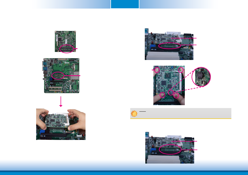
6. Grasping CD905-B by its edges, position it on top of the carrier board with its mounting
holes aligned with the bolts on the carrier board. This will also align the COM Express
connectors of the two boards to each other.
COM Express connectors on
CD905-B
COM Express connectors
on the carrier board
7. Press CD905-B down firmly until it is completely seated on the COM Express connectors of
the carrier board.
CD905-B
COM Express connectors
on the carrier board
Pressing points
BIOS ROM socket
Note:
The above illustration shows the pressing points of the module onto the carrier board.
Be careful when pressing the module, it may damage the socket.
CD905-B
The module is completely
seated on the carrier board
8. Verify that the module is firmly seated onto the COM Express connectors of the carrier
board.