Mechanical diagram, Hardware installation, Np900 – DFI NP900-B16C User Manual
Page 12
Advertising
12
2
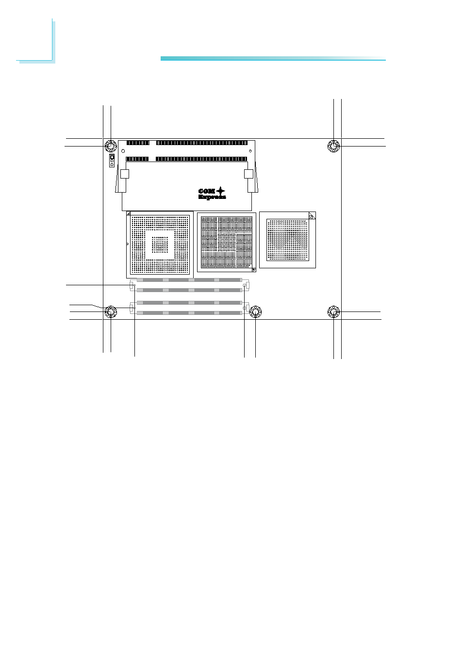
Hardware Installation
Mechanical Diagram
A
B
C
D
E
F
G
H
J
K
L
M
N
P
R
T
U
V
W
Y
AA
1
2345
89
10
11
12
13
14
15
16
17
18
19
20
21
67
27
28
1
2
3
4
5
6
7
8
9
10
11
12
13
14
15
16
17
18
19
20
21
22
23
24
25
26
A
B
C
D
E
F
G
H
J
K
L
M
N
P
R
T
U
V
W
Y
AA
AB
AC
AD
AE
AF
AG
AH
33
31
30
32
27
29
28
23
25
26
24
21
20
22
17
19
18
15
14
16
11
13
12
9
8
10
5
7
6
1
2
3
4
A
B
C
D
E
F
G
H
J
K
L
M
N
P
R
T
U
V
W
Y
AA
AB
AC
AD
AE
AF
AG
AH
AJ
AK
AL
AM
AN
NP900
0.00
0.00
2.00
14.00
4.00
4.00
12.50
70.20
76.00
117.00 121.00
4.00
0.00
87.00
121.00
91.00
117.00
87.00
0.00
91.00
4.00
Advertising