Hardware installation – DFI NP900-B16C User Manual
Page 30
Advertising
30
2
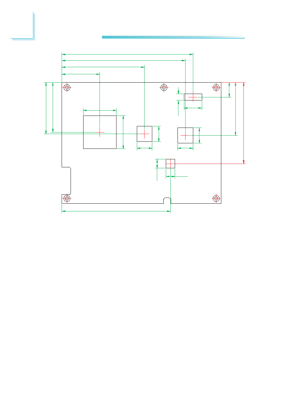
Hardware Installation
29.75
64.80
96.80
102.85
11.60
41.70
39.10
40.50
26.00
12.00
12.00
26.00
12.00
14.00
5.10
A
B
C
D
12.00
63.78
7.00
7.00
85.15
E
F
G
H
I
J
“A” to “E”
• Denotes the locations of the thermal pads.
“F” to “J”
• Denotes the locations of the mounting posts.
These mounting posts are used to mount the
heat sink and NP900-B16C assembly onto a car-
rier board.
• Use M2.5 screws with minimum length of 12 mm.
Bottom View
Advertising