Hardware installation – DFI COM630-B User Manual
Page 28
Advertising
28
2
Hardware Installation
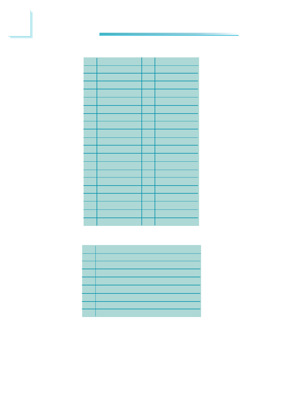
Pins
1
3
5
7
9
11
13
15
17
19
21
23
25
27
29
31
33
35
37
39
Function
GND
LVDS_Out3+
LVDS_Out3-
GND
LVDS_Out2+
LVDS_Out2-
GND
LVDS_Out1+
LVDS_Out1-
GND
LVDS_Out0+
LVDS_Out0-
GND
LVDS_CLK1+
LVDS_CLK1-
GND
LVDS_DDCCLK
LVDS_DDCDAA
Panel Power
Panel Power
Pins
2
4
6
8
10
12
14
16
18
20
22
24
26
28
30
32
34
36
38
40
Function
GND
LVDS_Out7+
LVDS_Out7-
GND
LVDS_Out6+
LVDS_Out6-
GND
LVDS_Out5+
LVDS_Out5-
GND
LVDS_Out4+
LVDS_Out4-
GND
LVDS_CLK2+
LVDS_CLK2-
GND
N. C.
N. C.
Panel Power
Panel Power
LVDS LCD Panel Connector
LCD/Inverter Power Connector
Pins
1
2
3
4
5
6
7
8
Function
GND
GND
Panel Inverter Brightness Voltage Control
Panel Power
+3.3V
Panel Backlight On/Off Control
+12V
+12V
Advertising