Hardware installation power connectors – DFI COM630-B User Manual
Page 38
38
2
Hardware Installation
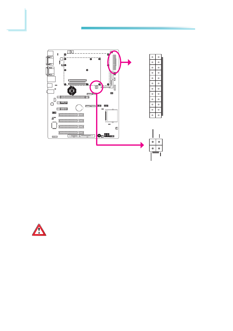
Power Connectors
13
12 24
1
+3.3VDC
+3.3VDC
COM
+5VDC
COM
+5VDC
COM
PWR_OK
+5VSB
+12VDC
+12VDC
+3.3VDC
+3.3VDC
-12VDC
COM
PS_ON#
COM
COM
COM
NC
+5VDC
+5VDC
+5VDC
COM
Important
The system board consumes a minimal amount of power. Due to its low
power consumption, you only need a 120W to 150W power supply. Every
power supply has its minimum load of power. If you use a greater than
150W power supply, the power consumed by the system board may not
attain its minimum load causing instability to the entire system.
Use a power supply that complies with the ATX12V Power Supply Design Guide
Version 1.1. An ATX12V power supply unit has a standard 24-pin ATX main power
connector that must be inserted into the 24-pin connector. The 4-pin +12V power
connector enables the delivery of more +12VDC current to the processor’s Volt-
age Regulator Module (VRM).
The power connectors from the power supply unit are designed to fit the 24-pin
and 4-pin connectors in only one orientation. Make sure to find the proper orien-
tation before plugging the connectors.
1
3
2
4
Ground
Ground
+12V
+12V