5 replacing shredder knives, 6 clearing a plugged rotor, 7 changing the discharge screen – Echo Bear Cat SC2206 User Manual
Page 16: 8 removing the rotor, Caution, Left right
2.75 INCH CHIPPER/SHREDDER
12
SERVICE & MAINTENANCE
bEForE insPECting or sErviCing any Part oF tHis MaCHinE, sHut oFF PoWEr sourCE,
anD MaKE surE all Moving Parts HavE CoME to a CoMPlEtE stoP.
WARNING
there is one optional discharge screen available with a
smaller mesh that will produce smaller-sized shredded
product. refer to the Parts section for this screen. to
change the discharge screen, proceed as follows:
remove the two 5/16" nuts and 5-1/2" bolts securing
1.
the discharge screen and pull the discharge screen
out from the bottom.
Clean any trash or debris from the screen area.
2.
insert the replacement screen into the bottom of the
3.
chipper body.
secure with two 5/16" x 5-1/2" bolts and 5/16" nuts.
4.
if too much material is fed into the chipper/shredder or
if the material is too large, the machine may become
plugged. to clear a plugged rotor, proceed as follows:
turn off the machine and let all moving parts come to
1.
a complete stop.
remove the eight 5/16" nuts holding the engine and
1.
plate to the frame (see Figure 5.1).
remove engine, plate and rotor assembly from the
2.
frame.
the rotor is connected directly to the engine
3.
crankshaft. if the rotor needs servicing, remove the
5/16-24 x 2-1/2" bolt, 5/16" spring washer and the two
set screws and key securing it to the crankshaft.
Pull the rotor assembly off the crankshaft.
4.
reverse the procedure to install the rotor.
5.
5.7 cHANGING THE dIscHARGE scREEN
5.6 cLEARING A pLuGGEd RoToR
5.8 REmovING THE RoToR
REMOVE
SCREW
SHREDDER
KNIVES
REMOVE
NYLOCK
NUT
.75 x .75
SPACERS
.75 x .90
SPACER
SHAFT
Fig. 5.3 Shredder knife and spacer arrangement on shaft
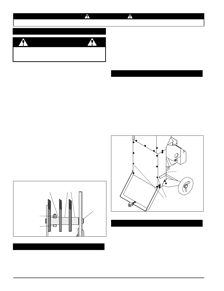
Fig. 5.4 Removing the discharge screen
DISCHARGE
SCREEN BOLTS
DISCHARGE
SCREEN NUTS
LEFT
RIGHT
the serrated shredder knives are designed to offer long
life and can be reversed if they become dull. For a
replacement kit, refer to the Parts section.
to reverse the knives or install a new shredder knife kit,
proceed as follows:
remove the eight 5/16" nuts holding the engine and
1.
plate to the frame (see Figure 5.1).
remove engine, plate and rotor assembly from frame.
2.
Working one shaft at a time, remove the 10-24 x 1-1/8"
3.
screw and 10-24 nylock nut from the knife spacer
located on the shaft.
Push the shaft out of the rotor assembly and remove
4.
the knife spacers. Keep track of the order the spacers
are installed on the shafts so they are returned to the
original location (see Figure 5.3). if the spacers and knife
sections are not installed properly, the rotor will be out of
balance and will not have proper shredding action.
reverse and reinstall the existing knives and spacers
5.
or install new knife sections and spacers onto the shaft.
secure the shaft with a new 10-24 x 1-1/8" screw and
10-24 nylock nut. torque to 36 in-lb.
repeat for the remaining shaft.
6.
replace engine, plate and rotor assembly and secure
7.
with eight 5/16" nuts.
5.5 REpLAcING sHREddER KNIvEs
never reuse the #10-24 nut and bolt. never reuse
shafts or spacers if they show signs of wear or abuse.
always install new parts when repairing.
cAuTIoN
remove
2.
left nut and bolt holding the discharge screen
in place (see Fig. 5.4).
reach up into the discharge chute and pivot that side
3.
of the discharge screen down.
Clean any trash or debris from the screen area, being
4.
careful not to touch the sharp blades.
Pivot the screen back up to its original position.
5.
secure with the 5/16" nut and 5-1/2" bolt.
6.