2 – the x3 rigging system components – EM Acoustics X3-DFSP self-powered downfill element User Manual
Page 18
Page 18 of 36
X3-SP User Manual
v1.0 May 2012
5.2 – The X3 Rigging System Components
The X3 flying system is designed to be very simple and intuitive to use. It is based around
three enclosure links, which are integral to each loudspeaker. Two of these links are
found recessed on the top of the loudspeaker, and are the primary load-bearing links.
The third link is recessed at the bottom rear of the enclosure, and is there to prevent
enclosures splaying apart at the bottom when the system is raised in the air.
Two optional additional flying hardware components are required – the FC-X3 enclosure
lift beam, and the MFB-X3 master flying beam.
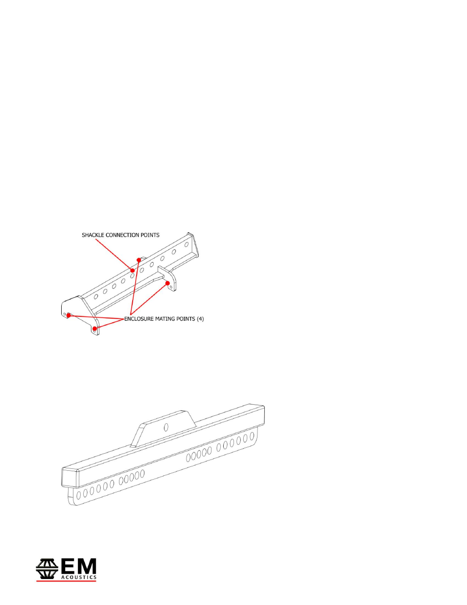
6.2.1 – The FC-X3 enclosure lift beam
The FC-X3 is a simple lift beam, which is the primary method of flying X3 systems. At
least one FC-X3 will be required to fly X3 enclosures in any configuration.
Different flying hardware is required depending on
whether the requirement is for single or dual pick-
up point, and how many enclosures are used. The
images below illustrate the required hardware for
different configurations. A 3.25 ton bow shackle is
supplied with each FC-X3, and by moving the pick-
up point forwards or backwards the array angle
can be changed. For down-tilt, move the shackle
to the rear. For up-tilt, move the shackle towards the front.
For X3 arrays comprising multiple FC-X3 lift beams, if a single pick-up point is required
then the MFB-X3 master flying beam should be used to create a single rigging point. 3.25
ton shackles supplied with the MFB-X3 link with those on the FC-X3 lift beams to create a
secure lifting system.
The tables in Appendix A on page 28 give the generated up or down-tilt angle
for different X3 array configurations. Please refer to these tables when
designing your X3 flown system.
MFB-X3 master flying beam