3 spare parts, 4 recommended spares, 5 tools required – Flowserve CPXS User Manual
Page 25
CPXS, CPXNS and CPXPS USER INSTRUCTIONS ENGLISH 71569250 07-11
Page 25 of 48
flowserve.com
c) The coupling should be checked for correct
alignment and worn driving elements.
Refer to the manuals of any associated
equipment for periodic checks needed.
6.2.3
Re-lubrication
Lubricant and bearing temperature analysis can be
useful in optimizing lubricant change intervals. In
general however, the following is recommended.
6.2.3.1
Oil lubricated bearings
Normal oil change intervals are 4 000 operating
hours or at least every six months. For pumps on
hot service or in severely damp or corrosive
atmosphere, the oil will require changing more
frequently. Lubricant and bearing temperature
analysis can be useful in optimizing lubricant
change intervals. The lubricating oil should be a
high quality oil having oxidisation and foam
inhibitors, or synthetic oil.
The bearing temperature may be allowed to rise to
50 ºC (90 ºF) above ambient, but should not
exceed 82 ºC (180 ºF) (API 610 limit). A
continuously rising temperature, or an abrupt rise,
indicate a fault.
Pumps that handle high temperature liquids may
require their bearings to be cooled to prevent
bearing temperatures exceeding their limits.
6.2.3.2
Grease lubricated bearings
The bearings are sealed for life. It is recommended
that they are renewed every 12 000 hours running
life or every 2 years, whichever is the sooner.
6.3 Spare parts
6.3.1
Ordering of spares
Flowserve keeps records of all pumps that have
been supplied. When ordering spares the following
information should be quoted.
1)
Pump serial number.
2)
Pump size.
3)
Part name – taken from section 8.
4)
Part number – taken from section 8.
5)
Number of parts required.
The pump size and serial number are shown on the
pump nameplate.
To ensure continued satisfactory operation,
replacement parts to the original design
specification should be obtained from Flowserve.
Any change to the original design specification
(modification or use of a non-standard part) will
invalidate the pump’s safety certification.
6.3.2
Storage of spares
Spares should be stored in a clean dry area away
from vibration. Inspection and re-treatment of
metallic surfaces (if necessary) with preservative is
recommended at 6 monthly intervals.
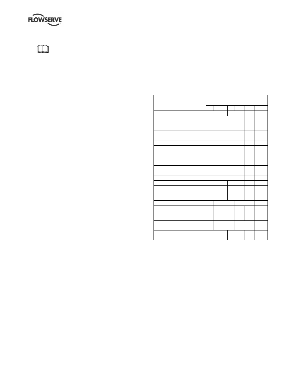
6.4 Recommended spares
For two years operation (as per VDMA 24296).
Number of pumps
(including stand-by)
Part no.
Designation
2
3
4
5
6/7
8/9
10(+)
2200
Impeller
1
2
3
30%
2100.1
Pump shaft
1
2
3
30%
3300.1
Bearing bush -
front
1
2
3
30%
3300.2
Bearing bush -
rear
1
2
3
30%
241.1
Tolerance ring
4
8
12
120%
3400
Sleeve (if fitted)
2
4
6
60%
3610
Thrust collar
2
4
6
60%
4590.5
Gasket - thrust
collar
4
8
12
120%
2923
Drive pin - thrust
collar
4
8
12
120%
3126
Shim pack
1
2
3
30%
220
Inner rotor
1
2
3
30%
230
Outer rotor
1
2
3
30%
224.1 or
224.2
Shell
(see note 1)
1
2
3
30%
3011
Ball bearing
2
4
6
60%
4590.1
Casing gasket
4
6
8
9
10
100%
4590.2 &
4610
Shell O-ring set
(see note 2)
2
3
4
5
6
60%
4590.3 and
4590.4
Remaining
gasket set
1
2
3
30%
252
Skid ring (if
fitted)
1
2
3
30%
Note 1: [224.1] PEEK (polymer). [224.2] metallic.
Note 2: [4590.2] gasket. [4610] secondary O-ring (if fitted).
6.5 Tools required
A typical range of tools that will be required to
maintain these pumps is listed below.
Readily available in standard tool kits, and
dependent on pump size:
•
Open ended spanners (wrenches) to suit up to
M 24 screws/nuts
•
Socket spanners (wrenches), up to M 48
screws
•
Allen keys, up to 10 mm (A/F)
•
Range of screwdrivers
•
Soft mallet