Flowserve CPXS User Manual
Page 27
CPXS, CPXNS and CPXPS USER INSTRUCTIONS ENGLISH 71569250 07-11
Page 27 of 48
flowserve.com
6.8.1
General
a) Lock and tag power source.
b) Ensure the work area is clean of grease, oil
and metallic chips or dust. Ferritic dust will
attract to magnetic assemblies.
c) Drilling, grinding or machining should NOT be
attempted near the work area.
d)
The dismantled magnet
assemblies [220 & 230] have a very strong
attraction. They should be handled separately
at a safe distance from each other and stored
in a clean area.
6.8.2
Dismantling frame mounted outer
assembly
a) Loosen the bearing housing footbolts.
b) Remove the 4 bolts [6570.3] holding the
bearing housing to the casing cover.
c) Insert 2 bolts into the threaded holes in the
bearing housing flange.
•
M14 x 60 mm for Model 80
•
M14 x 75 mm for Model 100
•
M12 x 140 mm for Model 150
d) Alternately jack the bolts into the flange,
32 mm (1.25 in.) for frame 80
53 mm (2.1 in.) for frame 100
105 mm (4.1 in) for frame 150.
This will release the outer rotor from the flux of
the inner rotor.
e) Slide the outer assembly [230] out past the shell
assembly.
f) Secure the outer assembly in a horizontal
position.
g) Using a dial indicator, determine the play of the
outer magnet carrier within the bore. If there is
contact between the outer carrier and the skid ring
[252], (if fitted), then the ball bearings [3011.1 & 2]
need to be replaced.
h) The nominal diametral clearance of the outer
rotor to the skid ring is 1 mm (0.04 in.)
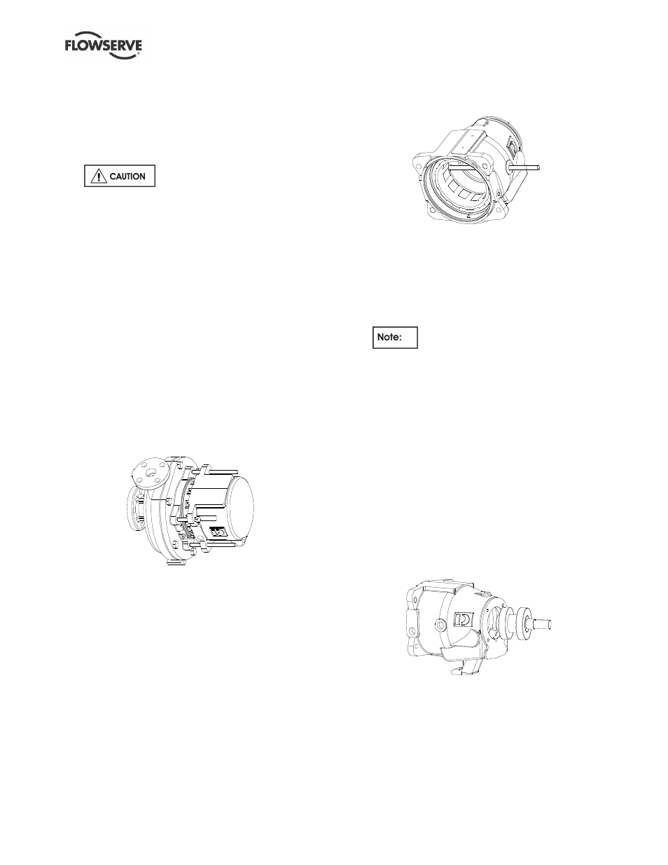
6.8.3
Removing outer rotor
a) The outer rotor is removed by first removing
the pipe plug from the side of the housing.
b) Rotate the outer rotor so that its 14 mm
diameter hole aligns with the plug hole. Insert
a bar or screw into the hole provided in the
bearing housing and outer rotor to lock the
rotor.
c) Place a coupling hub and key onto the shaft
coupling end and loosen the outer magnet
assembly [230].
Outer rotor is right hand thread.
d) Continue to unscrew and remove the outer
rotor from the large bore of the bearing
housing.
e) Scuff marks on the skid ring [252] can be
removed with a light file.
f) If the skid ring has excessive scuffing, it can be
removed by first sawing a small cut in the ring,
horizontally. Then place the end of a chisel
under the outer diameter and tap one side of
the cut up and over the other side. Continue
hammering inwardly until the ring comes loose.
g) Clean the groove into which the skid ring fits.
h) Remove the four screws [6570.4] fastening the
bearing end cover [3260] to the bearing
housing face. Remove cover and gasket
[4590.4].
i)
Slide the bearing shaft assembly out of the
bearing housing.
j)
Inspect both inboard [3011.1] and outboard
[3011.2] ball bearings. Replace as necessary.