Flowserve Machinery Components User Manual
Page 8
8
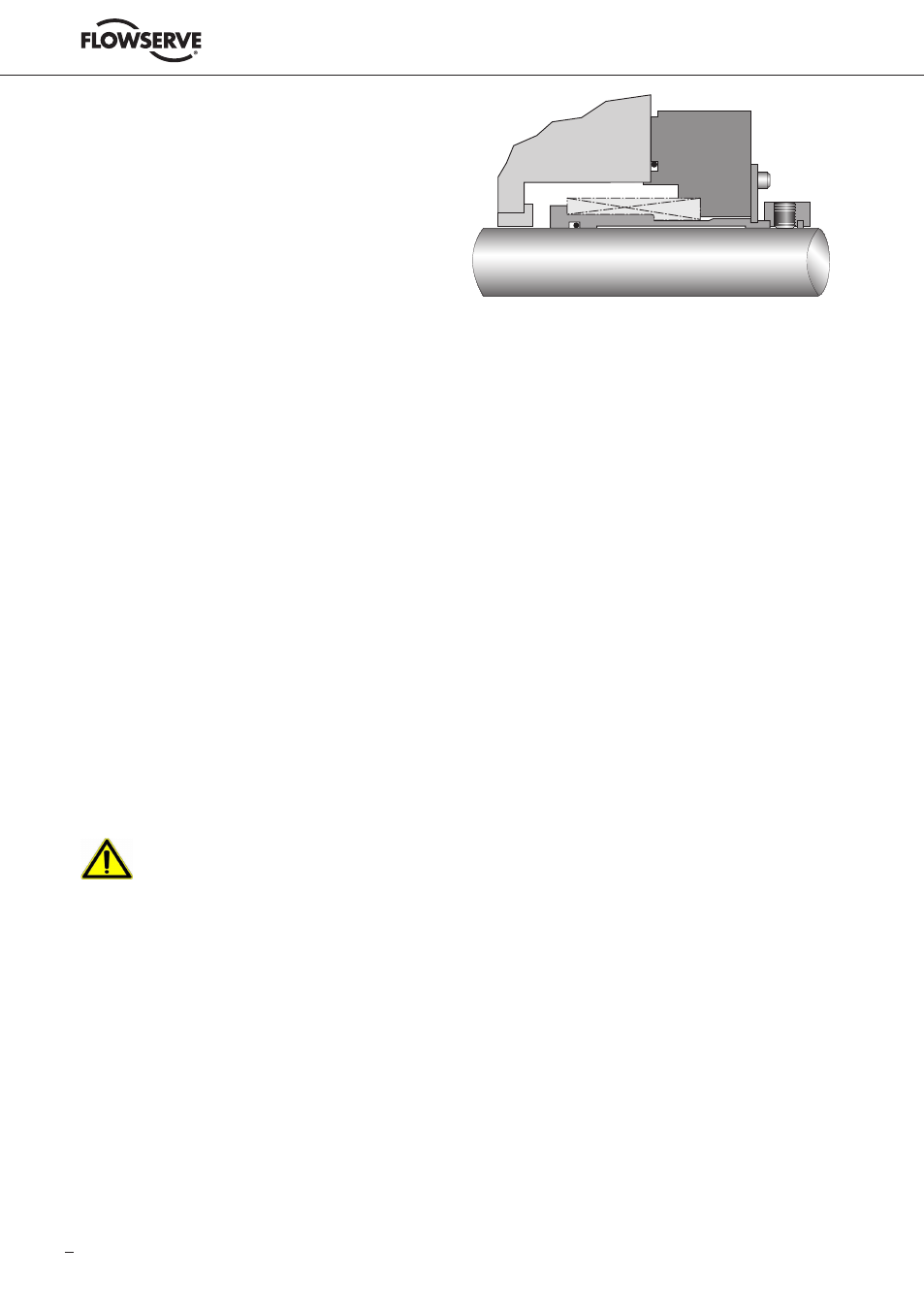
6.1 Installation of Cartridge Type Seal
with Setting Plates
See figure 6.
6.1.1 Check assembly drawing, bill of material and seal assembly prior to installation.
6.1.2 Install the seal onto the shaft and locate the gland against the face of the seal chamber.
6.1.3 Orient the ports on the seal gland(s) as indicated by the seal assembly drawing and
connecting piping.
6.1.4 Evenly torque gland bolts/nuts to prevent cocking of the gland or uneven gland pressure
against the seal chamber.
Do not tighten drive arrangement screws.
6.1.5 Complete the remaining equipment assembly including thrust bearings, if applicable.
6.1.6 Ensure the setting plates are correctly located and engaged.
Incorrect position of the setting plates can lead to malfunction of the mechanical seal
and consequent leakage of sealed product into the environment.
6.1.7 Tighten drive arrangement screws to the torque values shown on the seal assembly
drawing .
Inaccurate tightening of these screws can lead to unsafe situation as mechanical seal
may move out of the seal chamber when pressure is applied.
6.1.8 Assemble interconnecting piping as per API-plan and piping instructions as given
in para graph 7. See also (if applicable) auxiliary system installation and maintenance
manual.
6.1.9 Disengage setting plates from the sleeve and secure tightly in disengaged position.
Ensure that plates cannot fall back onto the sleeve as to prevent risk of contact between
rotating and static parts.
6.1.10 Inspect equipment and driver alignment in accordance with coupling and / or equipment
manufacturer's instructions.
6.1.11 After bringing the unit up to operating conditions (pressure and temperature), recheck
pump to driver alignment. Make adjustments as necessary.
!
!
Figure 6