Seal reference, Seal chamber requirements, Figure 1 – Flowserve PSS III Seal Durametallic User Manual
Page 2: Figure 2
While the PSS III has been designed for rugged industrial application
and ease of installation, it does require assembly in a clean environment
according to the following installation steps. No setting dimensions or
measurements are required to install the seal.
2
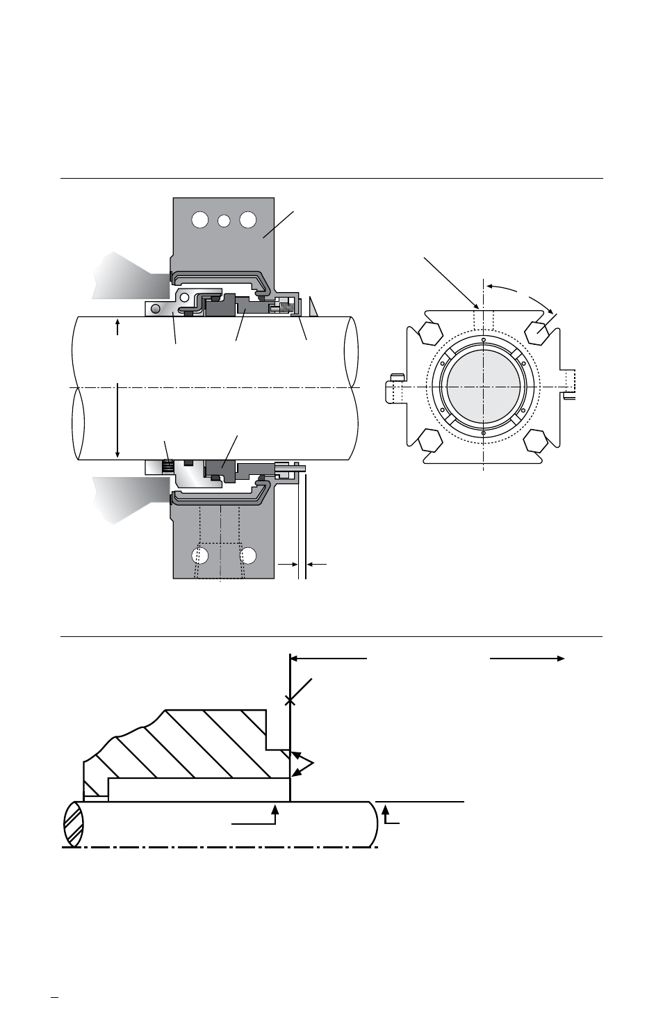
Seal Reference
Figure 1
45°
Shaft and
Seal Size
Seal
Drive
Stationary
Face
Set
Screw
Rotating
Face
1 - NPT
for Flushing
Gland
4.8 mm (0.19 inches) maximum
2.5 mm (0.10 inches) minimum Pin Extension
Seal Chamber Requirements
Figure 2
Centering
Device
To first obstruction
Face of seal housing to be square to the
axis of the shaft to within 0.0005 mm/mm
(0.0005 inch/inch) of seal chamber bore TIR
and have a 1.6
μ
m (63
μ
inch) R finish or better
a
Gland pilot can be at either of these
register locations, concentric to within
0.125 mm (0.005 inch) of shaft or
sleeve OD TIR
Seal housing bore to have 3.2 μm
(125 μinch) R finish or better
Sleeve or shaft finish to be
0.8 μm (32 μinch) R or better
a
a
• Bearings must be in good condition
• Maximum lateral or axial movement of shaft (end play) = 0.25 mm (0.010 inch) TIR
• Maximum shaft runout at face of seal housing = 0.05 mm (0.002 inch) TIR
• Maximum dynamic shaft deflection at seal housing = 0.05 mm (0.002 inch) TIR
Shaft or sleeve OD
+0.000 mm (+0.000 inch)
-0.050 mm (-0.002 inch)
+0.000 mm (+0.000 inch) API 610/682
-0.025 mm (-0.001 inch) DIN/ISO
ANSI
The images of parts shown in these instructions may differ visually from the actual
parts due to manufacturing processes that do not affect the part function or quality.