Gland installation, Size range torque, Gland to pump mounting bolt torques – Flowserve PSS III Seal Durametallic User Manual
Page 4
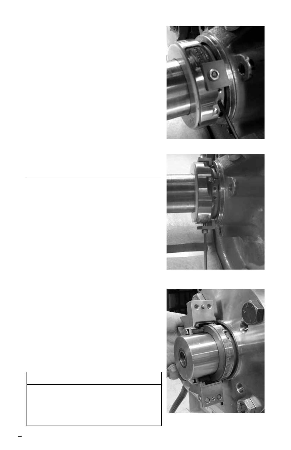
Step 4a With the setting devices against the
box face
, tighten the set screws. All
sizes have eight set screws. Tighten all
four located at one split joint. Then
tighten the four at the other split joint.
Tighten all set screws to 2.8 N-m
(25 in-lbs) for seal sizes up through
85.7 mm (3.375 inch) and 5.6 N-m
(50 in-lbs) for larger sizes.
b Tighten set screws a second time in
the same order.
c Check the face for joint alignment again.
Step 5 Remove setting devices by unscrew-
ing the socket head cap screw from the
seal drive.
Gland Installation
Step 6a Lubricate the fractured ends of the
stationary face, the seat gasket ends,
and the exposed surfaces of the gland
split joint gaskets with the enclosed lube.
b
Carefully assemble the gland halves
around the rotor
.
c Finger tighten the gland cap screws.
There should be a gap between the
halves of about 0.8 mm (0.03 inch).
d Finger tighten the gland bolts so the
gland is supported at the pump
mounting surface while the cap screws
are being tightened.
e Tighten the gland cap screws to
144 in-lbs, 16 N-m (12 ft-lbs).
f Tighten the gland mounting bolts
evenly
until the gland gasket is fully
compressed and the gland is squarely
seated against the pump box face.
4
Size Range
Torque
25.4-95.25 mm (1-3.750”)
33 N-m
(25 ft-lbs)
Above 95.25 mm (3.750”)
67 N-m
(50 ft-lbs)
Gland to Pump Mounting Bolt Torques
Step 4
Step 5
Step 6a