0 troubleshooting, Worcester actuation systems – Flowserve DRC-17 User Manual
Page 26
26
DataFlo Digital Electronic Remote Controller DRC17
WCAIM2058
5.9 Position/Control Select Input
Voltage Range: 10 to 30 VDC
Maximum Reverse Voltage: 5 volts
(on TB2 terminal 11 relative to terminal 12)
6.0 Troubleshooting
6.1 General
The following paragraphs and tables are a troubleshooting guide
for servicing the controller, should a malfunction occur. If the
problem cannot be solved, the unit should be returned to the
factory for service.
The first thing to be checked before proceeding to the
troubleshooting guide is to determine if the malfunction is in the
DRC controller circuitry or in the actuator motors. To do this, use
the following procedure:
Remove power from the DRC.
Inside the actuator housing, remove the RED and BLACK Motor
Driver Board leads from locations 3 and 4 of the terminal strip.
Remove the WHITE and BLACK power wires from the front side
of locations 1 and 2 of the terminal strip.
Tape all removed leads to prevent accidental contact.
Using a test power cable, apply power to locations 1 and 3 of the
terminal strip. The actuator should rotate counterclockwise
(CCW) until stopped by the CCW limit switch. Note that in 240
VAC models, the limit switches do not directly limit the travel. In
those models, insure that valve travel does not exceed normal
limits.
Using a test power cable, apply power to locations 1 and 4 of the
terminal strip. The actuator should rotate clockwise (CW) until
stopped by the CW limit switch. Note that in 240 VAC models,
the limit switches do not directly limit the travel. In those
models, insure that valve travel does not exceed normal limits.
If the actuator motors do not operate, check wiring from the
terminal strip through the limit switches to the motor and
capacitor. For 240 VAC models, check wiring from the terminal
strip to the capacitor and to the motor. Check switch continuity.
Check for an open motor winding, and check for a shorted
capacitor. If the problem in the actuator still cannot be
determined, return the unit for service. If the actuator functions
properly, then proceed to the troubleshooting guide.
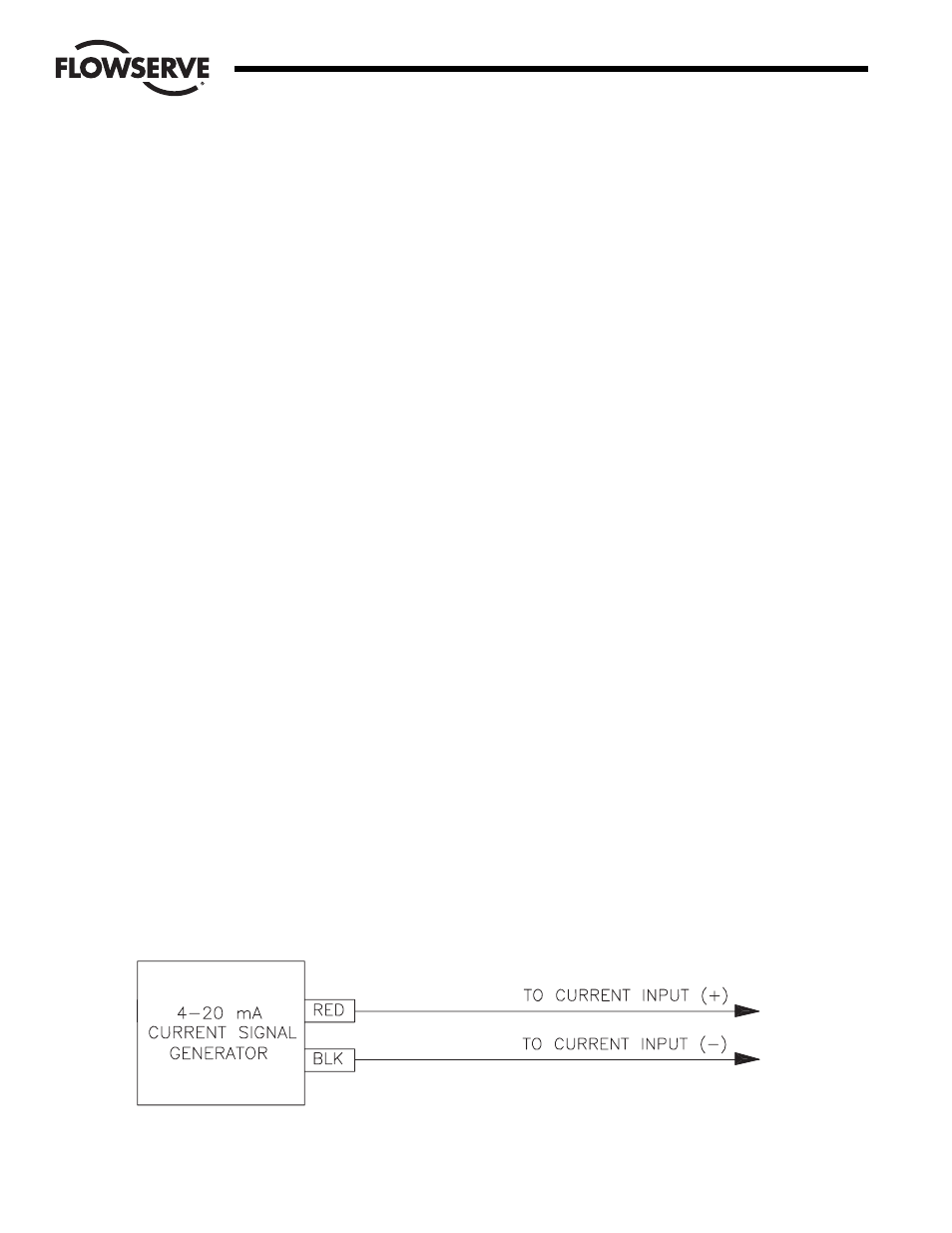
To facilitate troubleshooting the DRC, it is advantageous to
simulate the setpoint and process inputs whenever possible. For
potentiometer inputs, connect a local (or nearby) potentiometer
in place of the actual signal. For current inputs, use a current
generator such as the Worcester Controls 4-20 mA Current
Signal Generator (Part Number 15407).
6.2 Checking Proper Cam Location
The actuator cams should actuate the limit switches 1° to 3°
after the actuator stops at either the fully open or fully closed
position.
If the actuator is closed at 0°, the limit switch must activate by
the time the actuator is at the –1° to 3° position. Similarly, at the
open or 90° position, the limit switch must activate by the time
the actuator is at the 91° to 93° position.
6.3 Replacing the Motor Driver Board
The following procedure is provided if it becomes necessary to
replace the motor driver board.
Turn off the power supply to the DRC.
Disconnect all wires coming from the board to the terminal strip.
Remove the circuit board mounting screws, nylon washers,
circuit board and insulator board with rubber grommets from the
brackets.
Install the new circuit board onto the brackets using the
procedure described in step 3 above in reverse order. Tighten the
mounting screws so that the grommets are about half
compressed.
Make electrical connections as described in part 3.1.
Calibration is not required for the new motor driver board.
6.4 Symptom Table
Use the following table to help determine and correct problems.
The table represents a collection of typical symptoms and
sections to reference for guidance in correcting the problem. Use
the section(s) column to refer to further instructions for
correcting the problem.
Flow Control
Worcester Actuation Systems
Figure 17