Model 226-001 – GAI-Tronics 226-001 Industrial Telephones with Keypads User Manual
Page 4
Pub. 42004-337F
Model 226-001, 246-001, 256-001, and 276-001 Industrial Telephones with Keypads
Page 4 of 18
f:\standard ioms - current release\42004 instr. manuals\42004-337f.doc
06/12
Model 226-001
The mounting and wiring instructions for the Model 226-001 Public Access Telephone are as follows:
1. Remove the eight security screws
from the front panel. Remove the
front panel and set aside.
N
OTE
: There is a 7-foot half-
modular telephone cord attached to
the PCBA on the rear.
2. There are eight mounting holes in
the back of the enclosure in two 4-
hole patterns. Determine which hole
pattern will be used for mounting.
See Figure 5.
For best results, use the
7.875
4.0-inch hole pattern for
mounting to a wall (outside
pattern).
Use the 5.25
4.0 hole
pattern when using the Model
232-001 Pole Mounting Kit
(inside pattern).
3. Insert four hole plugs (provided) in the unused holes.
4. Position the enclosure on the mounting surface and
secure it with four fasteners.
The holes in the telephone enclosure accept 3/8-
inch screws or bolts.
The Model 232-001 Pole Mounting Kit includes
four 3/8-16
1-inch shoulder bolts with Teflon
seal washers.
NOTE
Use only the round head, hexagon
head, or pan head screws that are provided.
Do not use screws designed to be countersunk for
mounting the enclosure.
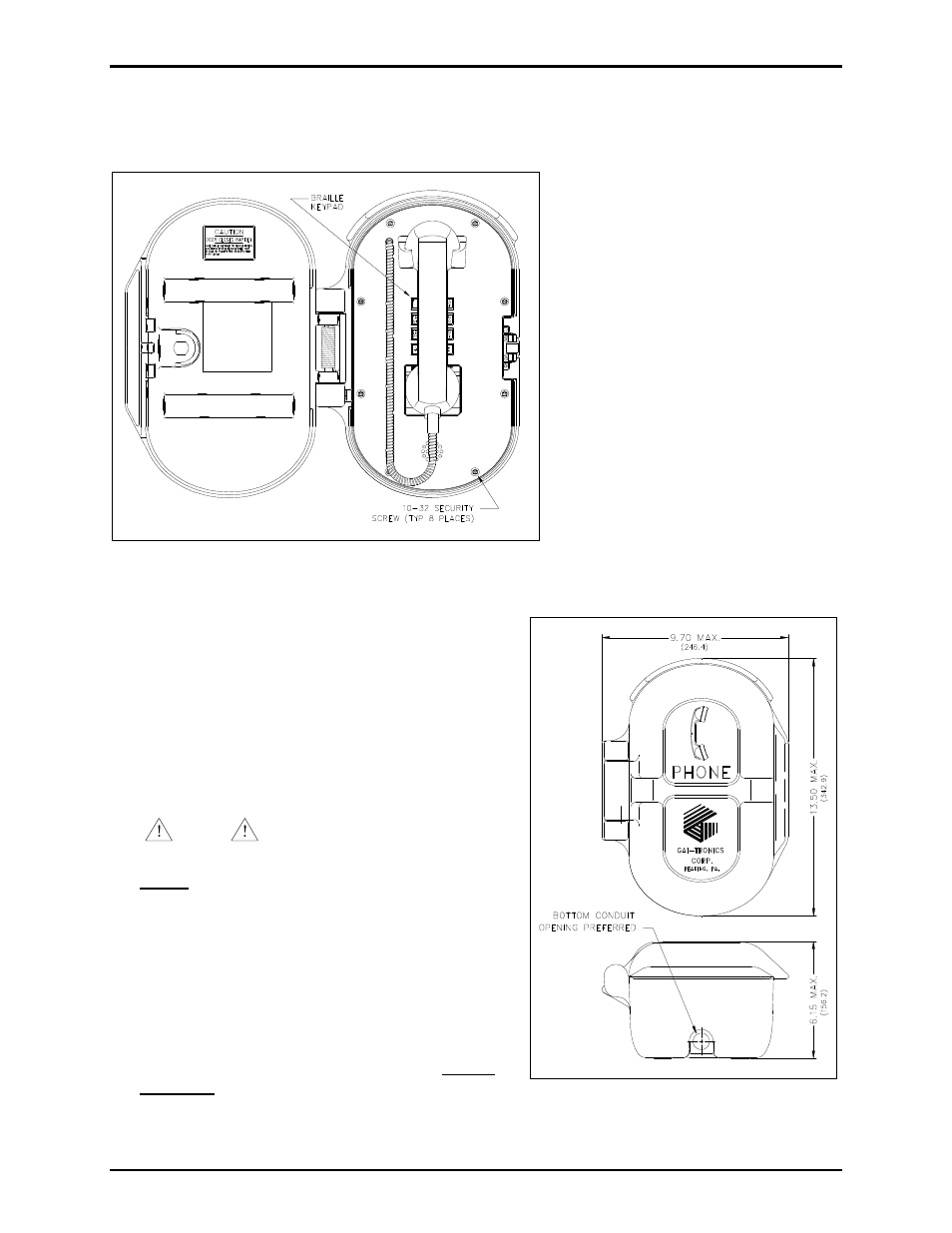
5. Install a conduit fitting in one of the ½-inch NPT
conduit entrances provided at both the top and bottom
of the unit, and insert the conduit into the fitting. (The
bottom location is preferred. See Figure 4.) Plug the
unused access hole using the 3/8-inch Allen drive plug
provided.
N
OTE
: Use silicone sealant or equivalent around
and inside all conduit entries.
Figure 3. Model 226-001 Public Access Telephone with
spring loaded door in the open position
Figure 4. Model 226-001 Outline