Block diagram – GAI-Tronics 7115-102 SmartSeries Desk-Edge Single and Multi-Party Subsets User Manual
Page 4
Advertising
Pub. 42004-642L2E
Model 711-102 and 7115-102 Desk-Edge Subsets
Page 4 of 9
f:\standard ioms - current release\42004 instr. manuals\42004-642l2e.doc
04/13
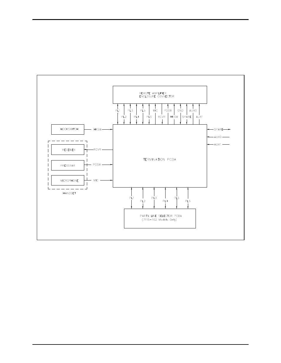
Block Diagram
As shown in Figure 3, the handset, hookswitch, party line switch (Model 7115-102 only), and auxiliary
input (optional) signals connect to the Subset Termination PCBA. The Subset Termination PCBA then
connects these signals to the appropriate terminals of the subset cable for connection to the
amplifier/amplifier enclosure.
Figure 3. Block Diagram
Advertising
This manual is related to the following products: