Specifications installation of components, Typical gas trains – Greenheck Maxitrol Series 14 User Manual
Page 3
3
Specifications
Installation of Components
Power Requirements: 24 VAC, 50/60 Hz Class II transformer
NOTE: Transformer secondary must not be grounded in any
portion of the circuit external to a Maxitrol amplifier. If existing
transformer is grounded, a separate isolated transformer
must be used. Electrical interference may effect
performance and/or damage equipment.
Ambient Limits:
Operating.....-40
o
to 125
o
F / -40
o
to 52
o
C
Non-operating.....-50
o
to 185
o
F / -46
o
to 85
o
C
Gases: Suitable for application in natural, manufactured, mixed
gases, liquefied petroleum gases and LP Gas Air Mixture piping
systems.
Vent: M411, 511, 611.....vertical vent outlet 1/8" NPT - 12A06
installed
MR212.....two vents located in upper housing, both equipped
Remote (or Dual) Selector: Install in control cabinet or
other chosen location. NOTE: Suffix letters must match,
e.g. TS114A must be used with TD114A. For wiring runs
longer than 200 ft. substitute ES261-1/ES261-2 for TD114.
The ES261s are a 2-piece version of the TD114. ES261-1
is a temperature setting dial only, ES261-2 must be
mounted at furnace location.
Discharge Temperature Sensor / Mixing Tube
Assembly: sensor housed in mixing tube, install in
discharge air stream.
Optional:
Dual Temperature Selector: see preceding Remote/Dual
selector.
Room Override Stat: mount in heated area not in direct
path of discharge air stream.
Inlet Air Sensor: install in convenient location upstream of
burner, in intake air duct.
Control wires connected to the Override Stat, Discharge
Air Sensor, or Remote Temperature Selector must not
be run close to or inside conduit with power or ignition
wires. Doing so may cause the unit to function
erratically or may destroy the amplifier. If shielded
wires are used, shield must be insulated and grounded
at the amplifier location only.
Wiring Run: If control wiring is inside conduit with
line voltage wiring, use shielded cable up to 100 ft.
For best results up to 200 ft., run control wiring in
separate conduit. For longer runs see Remote
Selector below.
Amplifier / Amplifier-Selector: contains the wiring
terminals and sensitivity adjustment - install in any
convenient location that is protected from the weather and
contaminated atmosphere.
Modulator (M) or Modulator-Regulator (MR) Valve: Mount in upright position in horizontal run of pipe, downstream of
other controls - a separate gas pressure regulator must be used with any modulator (M) valve.
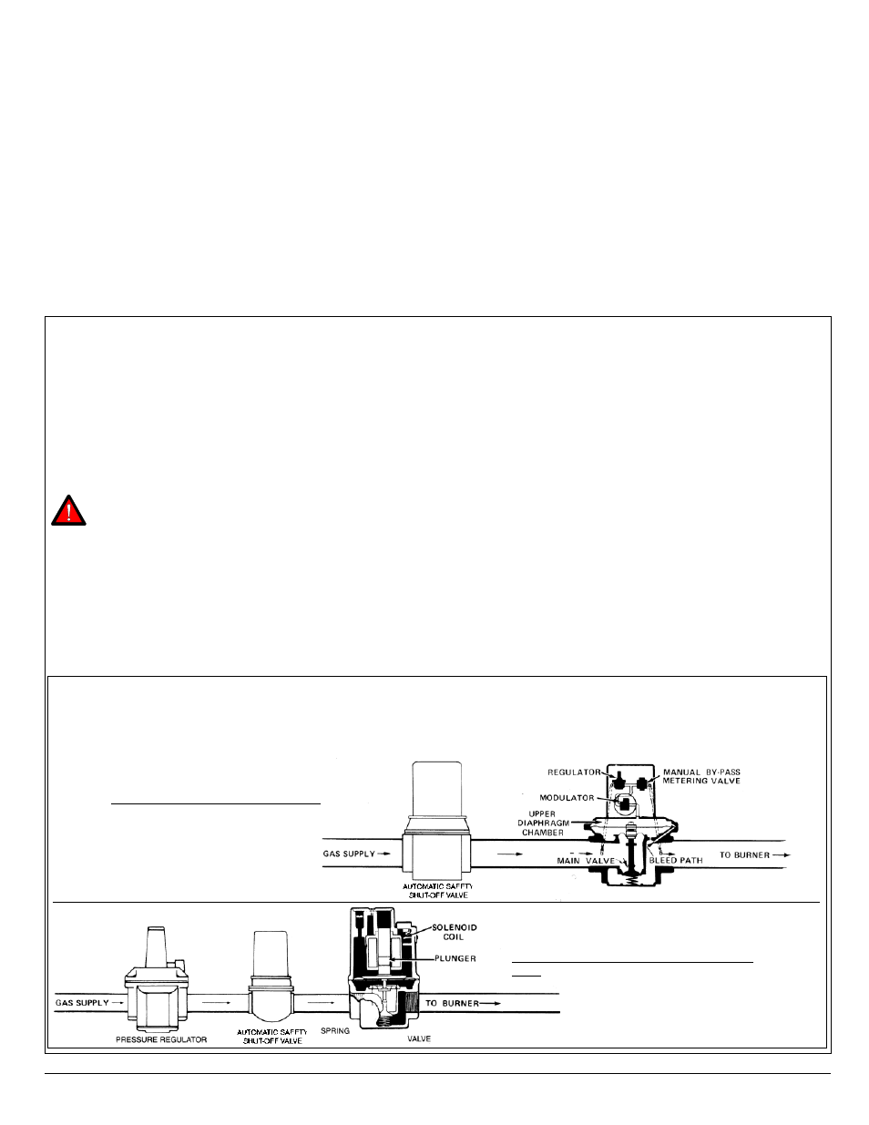
Typical Gas Trains
MR Valve: Modulator-regulator valve
M Valve: Regulator upstream of modulator
valve
Pressure Limits:
Maximum Discharge Pressure (M411, 511, 611).....7" w.c. /
17 mbar
Static Pressure Rating (M411, 511, 611).................5.0 psi /
345 mbar
Maximum Operating Inlet Pressure
M411, 511, 611.....1 psi / 70 mbar
MR212.....5.0 psi / 345 mbar
Maximum Emergency Exposure*
M411, 511, 611.....3.0 psi / 210 mbar
MR212.....12.5 psi / 862 mbar
* May not function properly at this pressure, but will suffer
no internal damage
©2007 Maxitrol Company, All Rights Reserved
with vent limiting means