Temperature calibration, Valve adjustments – Greenheck Maxitrol Series 14 User Manual
Page 7
A
B
M411, 511, 611 VALVE
High Fire Manifold Adjustments:
1. Disconnect wires from amplifier terminal #4, this causes
the valve to call for continuous high fire.
2. Adjust the pressure regulator to obtain the desired
manifold pressure (7"
w.c. maximum).
3. Reconnect the wires
to amplifier terminal
#4.
Low Fire or Bypass
Adjustments:
1. Disconnect wire from
amplifier terminal #8,
this causes the valve
to call for continuous
low fire.
2. Remove cap (A), and turn adjusting screw (B) to desired
low fire adjustment. (Clockwise rotation reduces
minimum flow rate.)
3. Replace cap (A), and reconnect wire to amplifier terminal
#8.
Temperature Calibration
NOTE: The components of this system are individually
calibrated and are not part of a matched set. It is
necessary to place an accurate temperature measuring
device as near the Discharge Air Sensor as possible.
Set the Remote Temperature Selector at least 10 degrees
above outside air temperatures.
If calibrating at the TD114 Remote Temperature
Selector: If measured temperature is below set
temperature, rotate the calibration potentiometer clockwise
until the correct temperature is obtained. If the temperature
is above the set point the potentiometer should be turned
counter-clockwise. Proceed slowly with the above steps so
as to allow the
temperature
measuring
instrument to catch
up with the change in
temperature.
If calibrating at the
A1014 Amplifier: Adjust
calibration potentiometer
(A), until temperature
reads the same as the
set temperature. If the
temperature is below
the set point, then
rotate calibration
potentiometer clockwise. If the temperature is above the
set point, rotate the potentiometer counter-clockwise.
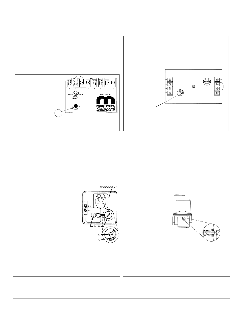
Valve Adjustments
(See bulletin MT2035 for additional M/MR valve information)
NOTE: Low fire adjustment should be checked whenever the high fire adjustment is changed.
MR 212 VALVE
High Fire Manifold Adjustments:
1. Disconnect wires from amplifier terminal #4. This
causes the valve to call for continuous high fire.
2. Remove seal cap (A), and turn
regulator pressure adjusting screw
to obtain desired manifold
pressure. (Clockwise rotation
increases pressure.)
3. Reconnect the wires to amplifier
terminal #4.
NOTE: If low fire bypass is on
maximum, the desired high fire outlet
pressure may not be achieved.
Low Fire or Bypass Adjustments:
1. Disconnect wire from amplifier terminal
#8, this causes valve to call for continuous
low fire.
2. Remove cap (B), and loosen lock screw (C). Turn (D) to
desired low fire adjustment. (Clockwise rotation reduces
minimum flow rate.)
3. Tighten set screw (C), replace cap (B) and reconnect
wire to amplifier terminal #8.
Calibration
potentiometer
A
7
©2007 Maxitrol Company, All Rights Reserved