Preliminary circuit analysis – Greenheck Maxitrol Series 14 User Manual
Page 5
Preliminary Circuit Analysis
For ease in troubleshooting, it is advisable to wire the
system as follows (this differs from the normal connection).
The Discharge Air Sensor is disconnected and replaced
with a 10,000 ohm, 1/2 watt test resistor (terminals 3 and
4). If inlet air sensor is being used, disconnect and replace
with a jumper. On units where the Remote Temperature
Selector is located a considerable distance from the heater,
it may be advantageous to connect the selector at the
heater location.
Connect a DC volt meter (capable of reading 0-24 V DC) on
the Modulator or Modulator-Regulator Valve terminals.
Set the temperature to the minimum dial setting. The DC
voltage should read 0 volts. The DC voltage should
gradually increase to at least 20 volts as you slowly rotate
the dial to the maximum dial setting. If these voltages are
obtained, the valve function can now be checked out.
The operation of the Valve with regard to voltage is as
follows: from 0 volts to approximately 5 volts, the
modulating valve should be on bypass flow with the heater
operating on low or minimum fire. From approximately 5
volts to 15 volts DC, the valve should be performing its
modulating function, and the heater should be firing at a
modulated flow rate between low and high fire, depending
upon the voltage. Above approximately 15 volts DC, the
Valve should be delivering full flow to the heater and the
unit should be on full fire. If the DC voltage is obtained on
the Valve terminals, but the heater does not respond as
described, the problem can be isolated to the valve itself or
to the gas control manifold of the heater (see check list,
pages 4 and 5).
In the event proper voltages are obtained, and the Valve
responds correctly to these DC voltages, the problem could
well be in the wiring leading to the Discharge Air Sensor or
the Discharge Air Sensor itself. This should be also
reviewed in the check list.
If the proper voltages are not obtained when wired as
instructed, the problem can be isolated to the electronics
and this may once again be reviewed in the check list.
After test, remove the test resistor and reconnect the
Discharge Air Sensor to terminals 3 and 4. If Remote
Temperature Selector has been moved return it to its
original position.
On A1014L1 and AD1014L1 amplifiers, the low fire start
duration is adjustable from approximately 0-30 seconds,
and begins timing after the amplifier has been energized.
High fire is delayed, and the M/MR valve remains in the low
fire setting position during the delay time period.
Use a small screwdriver to adjust the time delay
potentiometer.
Turn clockwise (+) to increase low fire start duration, and
counter-clockwise (-) to decrease low fire start duration.
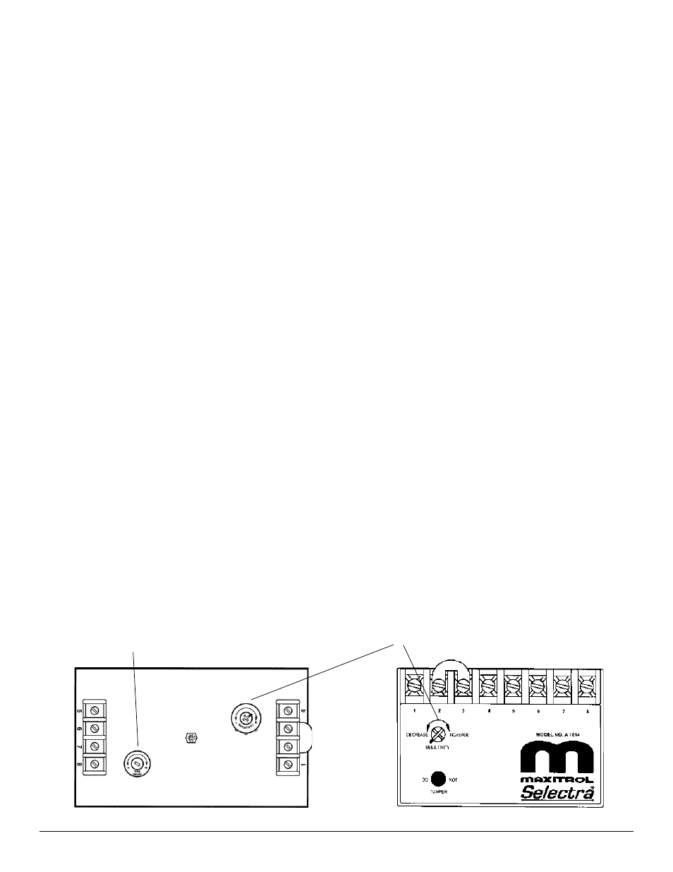
Sensitivity adjustment
Low Fire Start Time Adjustment
Sensitivity Adjustment
The sensitivity control will allow the user to control the
response of the system. Caution should be exercised in
the use of this adjustment. Under normal usage the pointer
should be located on the mark on the label.
If hunting is encountered (rapid oscillation), rotating the
sensitivity control counter-clockwise will dampen the
oscillation - stabilizing the flame.
DO NOT adjust unless necessary, because decreasing the
sensitivity will increase the temperature “DROOP” of the
system.
A1014 model amplifier
Time delay potentiometer
(A1014L1, AD1014L1 only)
A1014L1 model amplifier, and
AD1014, AD1014L1 model
amplifier-selector
(cover removed)
©2007 Maxitrol Company, All Rights Reserved
5