The local extender, Rear view – Guntermann & Drunck USB 2.0 Extender EL 4500 User Manual
Page 6
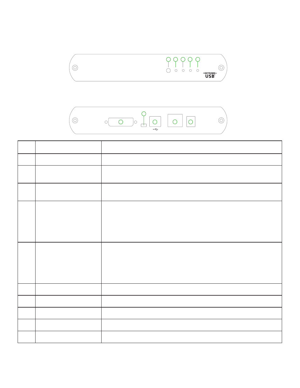
The Local Extender
The Local Extender connects to the computer using the included DVI and USB cable.
Front View
ITEM TYPE
DESCRIPTION
1
Pair (Button)
Reserved. Used if pairing a Local Extender to a Remote Extender.
2
Status LED (Green)
LED green indicates the system is ready. Green blinking indicates the system
is being configured. Off indicates there is no power applied to the unit.
3
Link LED (Green)
LED green indicates a valid link is established between the Local and Remote
Extender. Off indicates there is no link.
4
Video LED (Green/Amber)
LED green indicates the system has a valid link from the Host computer and
a valid link to the Remote Extender. Green blinking indicates video data is
being transmitted between the Local and Remote Extender. Amber indicates
there is no video source connected to the Local Extender. Blinking Amber
indicates an invalid resolution is being detected. Off indicates there is no link
between the Local and Remote Extenders.
5
USB LED (Green/Amber)
LED green indicates the system is properly enumerated on the host
computer. Green blinking indicates USB data is being transmitted between
the Local and Remote Extenders. Amber indicates that there is no USB
connection to the host computer. Blinking Amber indicates an over current
condition on one or more of the USB ports. Off indicates there is no link
between the Local and Remote Extenders.
6
DVI-D In
Accepts DVI-D connector for video input from the host computer.
7
Config
Reserved for company use only
8
Device Port (USB Type B)
Used to connect the Local Extender unit to the host computer.
9
Link Port (RJ45)
Accepts RJ45 receptacle for Cat 5 cabling (or better).
10
Power Port
Connects to the 5V, 3A power adapter.
6
5
Sta
tu
s
Lin
k
Video
US
B
1
2
3
4
Pa
ir
DVI-D In
Config
5V DC
Link
6
7
8
9
10
Rear View