IBASE MI912 User Manual
Page 28
Advertising
INSTALLATIONS
24
MI912 User’s Manual
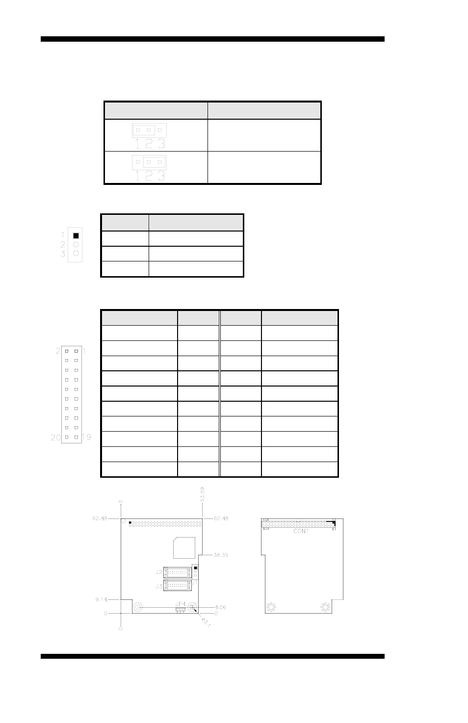
Headers and Connectors on Optional Daughter Cards
ID390 – JP4 LCD Panel Power Selection
JP4
Voltage
3.3V
5V
ID390 – J1 LCD Backlight Setting
Pin #
Signal Name
1
+12V
2
Backlight Enable
3
Ground
ID390 – J3 and J2 1
st
/2
nd
LVDS Channel Connectors
Signal Name Pin #
Pin #
Signal Name
TX0-
2
1
TX0+
Ground
4
3
Ground
TX1-
6
5
TX1+
5V/3.3V
8
7
Ground
TX3-
10
9
TX3+
TX2-
12
11
TX2+
Ground
14
13
Ground
TXC-
16
15
TXC+
5V/3.3V
18
17
ENABKL
+12V
20
19
+12V
Advertising
This manual is related to the following products: